


Additional Features:
- Test components and boards without power-ideal for catastrophic failures
- Get a picture of a component’s overall health-including intermittent problems
- Test gate-fired devices with a built-in pulse generator
- Non-destructive testing
- Input Selection: A, B, Alternate (variable rate)
- Test Frequencies: 50/60 Hz, 400 Hz, 2000 Hz
- Functions Range Selection: Manual or AutoScan; High Range Lockout
- Compare-A-Trace: Adjustable (0.5 Hz to 10 Hz)
- Pulse Generator Level: 0V to 5V; DC Mode: +DC or -DC; Pulse Mode: +Pulse, -Pulse, or both; adjustable duty cycle
General Specifications
- Line Voltage: 100 VAC, 115 VAC or 230 VAC, 50 or 60 Hz
- Power: 20 Watts maximum
- Display: 2.8 in (7.0 cm) diagonal CRT
- Dimensions: 11 in L x 9 in W x 4 in H (28 cm L x 23 cm W x 10 cm H)
- Operating Temp: +32°F to +122°F (0°C to +50°C)
- Storage Temp: -58°F to +140°F (-50°C to +60°C)
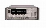
The advantage of Tracker technology
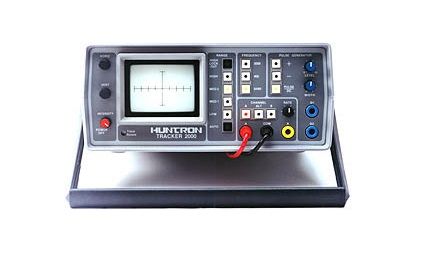
The Huntron Tracker 2000 provides advanced troubleshooting capabilities to simplify testing newer technology components such as CMOS and MOS circuits. Its built-in pulse generator lets you thoroughly troubleshoot gate-fired devices such as SCRs, TRIACs and optocouplers. By energizing the gate, you can test a component in an active mode.
You use a Tracker 2000 while the power to the circuitry you’re testing is turned off. So you avoid an accidental short that could cause further damage. It allows you to analyze the overall health of a solid-state component, which makes it perfect for finding leakage or substrate damage that has brought a system or PCB down prematurely.
Because it can compare suspect components to known-good equivalents, it’s also ideal for troubleshooting when documentation is missing or incomplete.
Real-world troubleshooting challenges
The Huntron Tracker 2000 is ideal for troubleshooting Programmable Logic Controls (PLCs). In troubleshooting multi-channel input modules, technicians frequently run into a damaged channel because the IC buffers, optocouplers and drivers have been overstressed. By using the pulse generator built into the Tracker 2000, you can quickly troubleshoot optocouplers and other gate-fired devices.
Simply compare signatures of one channel against another. You’ll usually find problems where you see differences in signatures. Likewise, you can compare multichannel outputs with the Tracker 2000. These devices usually fail when too much current is drawn through the logic section. To troubleshoot them, compare the signatures of ICs in one channel against those in another, looking for differences that indicate a problem.
Analog signature analysis
The Tracker works by applying a current-limited AC signal across two points of a component. The current flow causes a vertical deflection of the CRT trace, while the voltage causes a horizontal deflection. Together, they give you a unique current-voltage “analog signature” that represents the overall health of the device you’re testing.
Analyzing each signature, you can quickly tell if a component is good, bad or marginal.
| Manufacturer | Huntron |
|---|---|
| Condition | Used |