


Additional Features:
- Output: 0 to 20 volts DC, continuously adjustable, 0 to 500 milliamperes
- Input: 105 to 125 volts, 50 to 440 Hz, 40 watts (nominal) Regulation DC voltage change less than 100 microvolts for line variations of ±10% or load variations of 100% (at sense lead connection points)
- Ripple and Noise: Less than 100 microvolts peak-to-peak
- Source Impedance: Less than 0.2 milliohm at DC, 0.04 ohm at 20 KHz, 0.5 ohm at 1 MHz
- Recovery Time: Less than 10 microseconds to return to within 250 microvolts or 0.005% (whichever is greater) of the set voltage for a step change in rated load (1 microsecond rise time) of 10% to 100% or 100% to 10%; less than 40 microseconds to return to within 100 microvolts
- Stability: Better than 0.001% +100 microvolts per 8 hours; better than 1 millivolt per week (at constant line, load and ambient temperature after warm-up).
- Temperature Coefficient: DC output voltage change less than 0.001% or 50 microvolts (whichever is greater) per °C over the range of +15 °C to +45 °C, less than 0.002% or 100 microvolts (whichever is greater) per0 °C from °C from 0 °C to +15°C and from +45 °C to +60 °C
- Calibration Accuracy: Better than 0.1% +1 millivolt
- Current Limiting: 0 to 500 milliamperes continuously adjustable by a front panel control. A front panel push button permits easy adjustment without shorting the output terminals
- Calibrated decade voltage readout to four significant figures at outputs below 10 volts, to five significant figures above 10 volts. Interpolation of the last place is provided by a potentiometer with 10-microvolts resolution
- Provisions for rear-panel zero calibration (may be used to offset lead drop during remote sensing)
- Adjustable current limiting
- Self-restoring electronic overload and short-circuit protection
- All silicon-semiconductor regulator system
- Critical semiconductors and components maintained at constant ambient in temperature-controlled oven
- Accurate remote programming at 1000 ohms-per volt
- Front and rear access to output terminals.
- 100 hour pre-aging of power supply before test and calibration. Individual calibration data furnished with each unit
- Line and load circuits separately fused. Accessible at rear. Performance specifications based on anticipated ratings after 5 years service
- "Controlled-Parameter" semiconductor program insures long life expectancy. Features "controlled avalanche" silicon rectifiers and power transistors, pre-aged zener voltage references and transistors, noise-testing techniques for establishing predictable device reliability, derating to 50% of rated voltage and current, etc.
- Modular package construction suitable for rack mounting. Single or dual mounting in 5¼"x 19" panel
- Dimensions: 8-3/8 inches wide by 4-3/4 inches high by 8-15/16 inches deep behind the front panel
- Finish: The panel is finished in brushed aluminum and has etched black lettering. The housing is finished in blue-gray vinyl enamel. The chassis and bottom plate are gold iridite
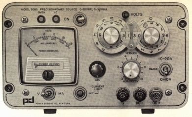
Output Terminals
- Front Panel: Three insulated binding posts for positive output, negative output, and chassis ground
- Rear Panel: Screw terminals on a molded barrier block for positive output, negative output, chassis ground, remote voltage programming and remote sensing
- Remote Sensing: Two terminals are provided on a rear panel barrier block for remote sensing of the voltage at the load
Parameter Specifications
- Remote Programming: Rear panel barrier block terminals are provided for remote programming of the output voltage. The ratio of the programming resistance to the output voltage is 1000 ohms per volt. The programming accuracy is better than 0.01% of the resistance value, including the resistance of the programming leads
- Metering: Front panel volt-ammeter permits monitoring output voltage or current with an accuracy of ±2% of full scale. This accuracy is considerably less than that of the power source
- Circuit Protection: The AC line and DC load circuits are separately fused. The fuses are accessible at the rear of the unit
Indicator Lamps
- AC Lamp: Lights when AC toggle switch is set to ON and power is applied to the unit
- OVEN Lamp: Lights when AC input is applied and oven heater is energized (operates even when AC toggle switch is turned off). Lamp cycles on and off as oven maintains constant temperature environment for critical components
- +10 V Lamp: Lights when RANGE switch is set to 1O-20V position to indicate that output is 10 volts plus the dial readout
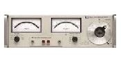
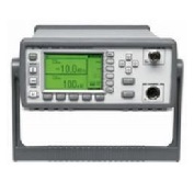
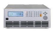
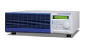
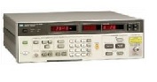
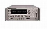
The Power Designs Model 2005 is a precision DC power source designed to supply an extremely stable 0 to 20 volt, 0 to 500 milliampere output. The instrument combines the accuracy of a precision calibrator with the power capability of a general-purpose regulated supply. Two dual, concentric decade switches provide a digital readout of the selected output voltage to within 0.1% +1 millivolt of the selected value. A 1-millivolt range, single-turn potentiometer permits interpolation of the last place. This potentiometer has a resolution of 10 microvolts. A toggle switch selects the range of the dial readout; either from 0 to 10 volts, or from 10 to 20 volts. The output voltage of the supply may be remotely programmed with the same accuracy, using an external resistance. The supply also includes provisions for remote sensing of the output voltage at the load. Compact and light, the power source is self-contained in a portable housing designed for bench use. The modular construction of the Model 2005 makes it suitable for rack mounting. Panel adapters are available for mounting one or two units in a standard 19-inch rack having a panel height of 5 1/4 inches.
| Manufacturer | Power Designs |
|---|---|
| Condition | Used |
| Current | 500 mA |
| Voltage | 20 V |
| Power | 1 W |