


Additional Features:
- Wide band cover: 10 kHz to 5.4 GHz
- Low residual FM noise: 0.3 Hz; RMS at 1 GHz
- Low spurious signals: –90 dBc non-harmonics
- Low phase noise: –140 dBc/Hz at 1 GHz
- Comprehensive modulation modes
- +13 dBm output (+19 dBm optional)
- 0.1 Hz to 500 kHz modulation oscillator
- Comprehensive frequency and amplitude sweep capabilities
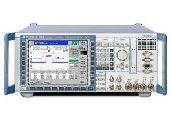
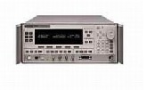
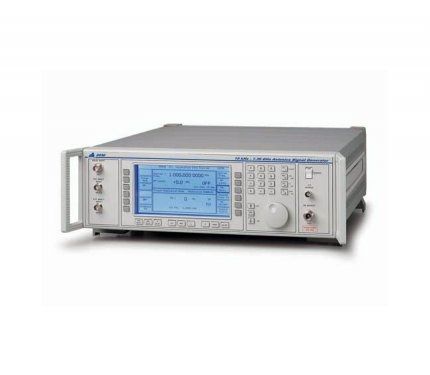
The 2040 series of low noise signal generators covers a wide range of frequencies from 10 kHz to 1.35 GHz (2040), 10 kHz to 2.7 GHz (2041) and 10 kHz to 5.4 GHz (2042). With a choice of operating modes, two low noise modes for improved SSB phase noise and normal mode for increased flexibility, the 2040 series can be used in a wide variety of applications. Microprocessor control coupled with a large screen dot matrix display provides ease of use via menu driven displays. Set up time is further reduced by recalling previously stored instrument settings from the non-volatile memory. Remote programming via the GPIB is provided as a standard feature, allowing the instruments to be incorporated in automatic test systems.
Excellent Spectral Purity
The excellent noise characteristics and the low level of spurious signals of the 2040 series enable the instruments to be used with confidence for a wide range of critical measurements.
Low SSB Phase Noise
With a specified SSB phase noise performance of better than –140 dBc/Hz at 20 kHz offset from a carrier of 1 GHz, the 2040 series of signal generators is easily able to measure UHF receiver selectivities beyond 90 dB.
The low residual FM noise figure (less than 0.3 Hz RMS at 1 GHz) gives the 2040 series the capability of measuring UHF receiver signal to noise ratios as high as 80 dB.
Low spurious signal content
A specified non-harmonic spurious signal content of –90 dBc ensures the suitability of the 2040 series for the most demanding measurements on modern receivers and RF systems.
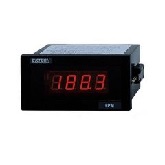
Display
A large screen, dot matrix liquid crystal display, with backlighting, offers excellent clarity and low power consumption.
The parameters displayed on the screen depend on the operating mode selected; for example, in the Signal Generator mode, carrier frequency, modulation and RF level are shown in separate horizontal regions. Status information is also shown with error messages being displayed in a single line at the top of the screen.
Frequency selection
Carrier frequency entry is selected via a soft key option on the signal generator screen and data is then entered directly via the keyboard. Frequency is resolved to within 0.1 Hz across the complete range of the instrument. Carrier frequencies can be stored in the non-volatile memory for recall at any time. A CARRIER ON-OFF switch is provided to completely disable the output.
RF Output
RF output up to +13 dBm can be set by direct keyboard entry with a resolution of 0.1 dB or better over the entire range. An extended hysterisis facility allows for extended electronic control of RF output level without introducing mechanical attenuator transients when testing squelch systems and an overrange facility allows the generator to produce RF levels above the normal operating range. A high output option is available to extend the maximum calibrated level to +19 dBm on 2040.
A low intermodulation mode can be selected which disables the RF levelling system and improves the intermodulation performance when combining the outputs of two signal generators.
50 W Protection
An electronic trip protects the generator output against reverse power of up to 50 W, preventing damage to output circuits when RF or DC power is accidentally applied. This feature contributes to long unit life and low cost of ownership.
Versatile Modulation Capabilities
Comprehensive amplitude, frequency (plus Wideband FM), phase and optional high-speed pulse modulation are provided for testing all types of receivers.
Modulation Oscillator
An internal modulation oscillator is provided with a frequency range of 0.1 Hz to 500 kHz, resolved to 0.1 Hz. In addition to the normal sine wave output an alternative triangular or square waveform may be selected for sweep applications. A second oscillator may be added as an option. Two independent BNC inputs on the front panel allow external modulation signals to be mixed with the internal signal(s) allowing a maximum of four modulation channels to be active at one time.
Modulation Modes
Four modulation modes are provided – single, dual, composite and dual composite. In the single mode only one type of modulation can be active at any time. Selecting alternative modulation cancels any other active modulation. In the dual mode two types of modulation may be obtained allowing one form of frequency modulation to be combined with one form of amplitude modulation. In the composite mode, only one type of modulation can be active, and is fed by two independent channels. The dual composite mode combines the facilities of the dual mode with the composite mode and provides two types of modulation each fed from two sources.
Frequency and Phase Modulation
The wide range frequency modulation capability provides a 1 dB bandwidth of 300 kHz and provides FM deviation up to a maximum of 1 MHz for frequencies up to 21 MHz, 1% of carrier frequency elsewhere. Phase modulation is also available with a 10 kHz bandwidth up to a maximum of 10 radians.
Both AC and DC coupled FM are available and in the DC coupled mode a patented offset correction system eliminates the large carrier frequency offsets that occur with normal signal generators. As a result, the 2040 series signal generators can be used confidently for testing tone and message paging equipment.
Wideband FM
Broadband frequency modulation with a 3 dB bandwidth of 10 MHz is provided via a rear panel BNC socket. This is ideal for tests on equipment using frequency shift keying for high speed digital transmission.
Amplitude and Pulse Modulation
Amplitude modulation with a 1 dB bandwidth of 30 kHz and with modulation depths of up to 99.9% is available with a resolution of 0.1%. Fast pulse modulation is available as an option with rise and fall times of less than 25 ns and a 70 dB on/off ratio.
Modulation Levelling
An automatic level control facility is provided for both of the external modulation inputs and provides correctly calibrated modulation for input levels varying from 0.7 to 1.4 V RMS. Hl and LO indications show when the input level is outside the range of the ALC system.
Tone Signaling
The signaling facility allows testing of radios with DTMF, sequential and subaudible tone capability. A wide range of tone system standards are built in and provision is also made for user definable standards to cover special requirements. Tone sequences can be set up with up to 16 tones in length and the complete sequence can be sent from 1 to 9 times or set to repeat on a continuous basis. Subaudible tones are normally used in the composite modulation mode where the modulation level for the tone and the inband modulation can be set independently.
Delta Display
The Delta menu allows the increment values for all the parameters to be set and also includes a TOTAL SHIFT key to show the variations in the parameters from their last keyed in value, a RETURN key to reset the selected parameter to its start value and a TRANSFER key to update the parameter value to equal the shifted value.
Frequency and Level Sweep
The digital sweep capability of the 2040 series allows dynamic testing of systems and includes capabilities for sweeping carrier frequency, RF level, LF frequency and LF level. Four parameters are entered to specify the sweep – start value, stop value, number of steps and time per step.
Markers and Ramp Output
Five markers may be defined and a marker output is provided on a rear panel socket together with a 0 to 10 V ramp signal for driving the X axis of an oscilloscope or X-Y plotter.
Option 8 provides additional sweep capabilities which allow the step size, step time and RF level to be entered.
Start/Stop
A single key press starts the sweep and a horizontal bar graph on the display shows the progress of the sweep. The sweep can be stopped at any time and the Up/Down keys used to step forwards or backwards for search purposes. Transfer of the current sweep value into the signal generator or LF modes for more detailed analysis is also possible. The sweep facility can be used in conjunction with a simple X-Y display unit, an oscilloscope or an X-Y plotter.
Powerful Non-Volatile Memory
True non-volatile memory needing no battery back-up is fitted to the 2040 series and is used to store details of instrument settings and calibration information.
Instrument Settings
Details of instrument settings are stored in four areas of memory. One area stores 50 complete instrument settings (including data on parameters which are not currently active), a second area stores 50 partial settings (consisting of details about the currently active parameters), a third area stores details of 100 carrier frequency values and a fourth area stores details of 20 sweep settings. Facilities are provided to prevent the memories from being accidentally overwritten and for recalling a specified memory at switch-on.
Calibration Data
In addition to storage and recall of measurement settings, the non-volatile memory contains data on instrument status and calibration. All calibration data on RF level, FM accuracy, internal frequency standard adjustment and modulation are retained and may be altered from the front panel or via the GPIB after disabling the software protection. Status information stored includes the identity string (type and serial number), choice of internal/external standard, GPIB address, elapsed time and a date alarm for calibration due reminders.
GPIB 488.2 Programming
A GPIB interface is fitted as standard so that all functions are controllable over the bus. The instruments function as talkers as well as listeners and the interface has been designed in accordance with the IEEE 488.2 standard.
Simple Calibration
The 2040 has a two-year recommended calibration interval, with all routine calibration adjustments carried out without removing the instrument covers. The calibration display is available via soft key selection in the utilities menu.
| Manufacturer | IFR |
|---|---|
| Condition | Used |
| Frequency | 5.4 GHz |