


Additional Features:
- -320 to +320 VDC, 0.625 A DC Power Module for the AT8000A/B
- 0.625 A maximum from 320 VDC to 240 VDC and derating linearly to 0.375 A maximum at 0 VDC
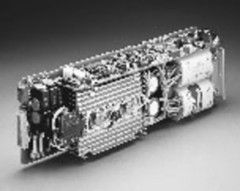
A master/slave module combination is a set of two (2) to six (6) DC Power Modules internally connected together to function as a single channel. One master module Is required for each channel. One or more, up to five (5), slave modules may be installed to interconnect with its respective master module for increased output current (power).
A master module is identified by verifying the presence of integrated circuits U7, U8, U18, U 19, and U21 on its DAC board (top most board of the module). Slave modules obtain their programming information via their respective master modules and not from the processor directly. Thus, slave modules do not have these particular integrated circuits installed. Master modules may be factory modified to become slave modules.
The master/slave module combination should be installed into adjacent channel number slots to minimize the length of ribbon cable connecting the modules together. A master module may be installed in any slot relative to its slave modules. A ribbon cable carries programming information from the master module to its corresponding slave modules via their respective J1 IC socket connectors. No output power is present on the ribbon cable.
The location of the master module determines the channel number of the master/slave combination. If a master DC Power Module is installed in slot 1, then its channel assignment is channel 1. Similarly, a master installed in slot 2 yields channel 2, etc. A slave module uses the channel assignment number of its corresponding master, regardless which slot the slave occupies.
Should your Model AT8000 have one or more expansion chassis drawers, you will want to verify (or set) the Channel Group Select Switch located on the rear of the respective chassis.
The master chassis processor supports 16 channels no matter how many extension drawers are used. Each channel assignment is determined by the placement of a master module. Slots 1 through 6 corresponds to channels I through 6, respectively, when the Channel Group Select Switch Is set to position 'A'. To obtain channel assignments 7 through 12, merely set the corresponding Group Select Switch to position 'B'. Similarly, position 'C' corresponds to channels 13 through 16.
It is normal to have any two or more chassis drawers set to the same Group Select Switch position provided that master modules are not placed in identical slot numbers. There is no channel conflict concern if a master of one chassis occupies the same slot number as a slave of another chassis. Repeating, a master module slot together with its chassis Group Select Switch determines the channel assignment.
The outputs of the master/slave modules must be connected together in parallel at their respective output terminals and thus provide current that is equal to the current of a single module multiplied by the number of modules in the master/slave combination. This configuration is limited to modules of identical voltage arid current characteristics. The remote sense input should be connected only to the master module because it alone senses remotely and regulates both itself and associated slave modules. The remote sense inputs of slave modules are not used.
| Manufacturer | Elgar |
|---|---|
| Condition | Used |
| Current | 625 mA |
| Voltage | 320 V |
| Power | 200 W |