


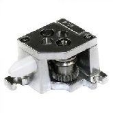

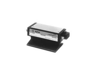
Additional Features:
- Frequency range (GHz): dc to 40
- Attenuation range: 0 to 11 dB, 1 dB steps
- Insertion loss (dB): 0.8 dB + 0.04 dB/GHz
- Maximum SWR Std. (Opt. 006): 1.3 (1.5) to 12.4 GHz; 1.7 (1.9) to 34 GHz; 1.8 (2.0) to 40 GHz
- Repeatability life: 0.03 dB max. 5 million cycles per section
- Maximum RF input power: 1 W avg. 100 W peak 2 (10 μs max)
- Supply voltage range: 20 to 30 Vdc
- Supply voltage (nom): 24 Vdc; 125 mA
- RF connectors: Std.: 2.4 mm (f)
- Programmable
- SWR
- Accuracy
- Repeatability
- Life
Applications
- Reducing signal levels
- Matching impedances of sources and loads
- Measuring gain or loss of a two-port device
SWR
Most attenuators use some form of distributed thin-film attenuating element, designed to operate over multi-octave ranges and for low SWR match at input and output. The SWR characteristic is controlled with careful design of the element as well as the transition from RF connector to the element’s planar geometry. When an attenuator is inserted into a test network, the interaction of its SWR and the network SWR results in frequency-varying mismatch, which degrades the accuracy of the measurement. The amount of variation often exceeds the flatness specification of the attenuator. As an example, if at a given frequency, a 3 dB attenuator with SWR of 1.22 at each port is inserted into a microwave network that has a source and load SWR of 1.35, the variation from the expected 3 dB change could be as great as ±0.5 dB. This change is due to SWR alone and points out the importance of the SWR specification in a precision attenuator.
Accuracy
The accuracy of an attenuator directly affects the uncertainty of the measurement where the attenuator is used. In many measurement and metrology applications, attenuators are the basic standard against which other components and instruments are calibrated.
Agilent attenuator accuracy specifications always include the effect of frequency response. And, Agilent attenuators use “edgeline” coaxial structure technology to achieve low-insertion loss and SWR resulting in better accuracy. Agilent attenuators achieve flat-frequency response and high accuracy through the use of thin-film attenuator cards. These cards are composed of high-stability tantalum nitride resistive film, deposited on sapphire or alumina substrates.
Advanced design and state-of-the-art processes in the deposition stages allow precise control of the geometry and thus the attenuation value. The result is very flat frequency response and greater accuracy.
Ultimate specified accuracy of RF/microwave attenuators is limited by the accuracy to which National Institute of Standards and Technology (NIST) can measure, plus the uncertainty of the measurement transfer process which calibrates the production test equipment. At Agilent, performance to specifications is verified by fully testing each attenuator with an ATE system including an automatic network analyzer (ANA). In turn, the ANA is periodically calibrated using standards traceable to NIST.
Each published specification has been established using a “specification budget” process. This process provides for “guardbands” to account for transfer uncertainties between NIST, Agilent Metrology Labs, and the Agilent production test systems.
Repeatability
Fixed attenuators are often used as standards of reference in microwave measurements. Therefore, the accuracy of the measurement depends not only on the reference accuracy but on the repeatability of the insertion processes. Typical production test situations might require hundreds of connects/disconnects per day. So, measurement repeatability depends strongly on the connectors used. Agilent attenuators use precision type-N and APC-7 connectors, with repeatability that exceeds the International Electrotechnical Commission (IEC) standard for 7-mm connectors. For higher frequencies, Agilent uses 3.5-mm connectors that are fully SMA compatible, but are more rugged and repeatable than SMA. For applications to 50 GHz, Agilent uses 2.4-mm connectors that also have larger mating surfaces for rugged and repeatable connections. Design verification testing of 3.5-mm connectors showed virtually no test deterioration even after 1000 connections. For step attenuators, the repeatability of the internal RF connections is also of concern. Agilent uses an “edgeline” transmission line structure in which the outer conductor is a continuous ground plane and only the center conductor is switched to insert or remove an attenuation step.
Keys to achieving long-term repeatability include precision control of all dimensions that affect contact pressure, careful selection and control of plating processes, and careful monitoring and control of the assembly process. The result is a step attenuator with repeatability specified at 0.03 dB maximum over 5 million cycles per section.
Life
The life of step attenuators is usually specified in cycles; i.e., the number of times a given attenuator section switches from one position to another and back. Agilent determines life by cycling attenuators to the point of degradation. Typically, Agilent attenuators in life cycle tests perform to specification for at least twice as many cycles as warranted. Agilent step attenuator families have a specified life of 5 million cycles per section. This long life results in lower cost of ownership by reducing periodic maintenance, downtime, and repairs.
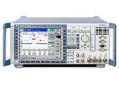
| Manufacturer | Agilent, HP, Keysight |
|---|---|
| Condition | Used |
| Frequency | 40 GHz |