Specifications
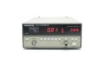
The Boonton 4220 is a single channel Power Meter that offers excellent performance. A built-in power reference, coupled with low instrument noise and excellent linearity, allows levels from -70 dB m to +37 dBm to be accurately measured with confidence. A wide choice of power sensors, both coaxial and waveguide, accept frequencies from 100 kHz to 100 GHz. The ability to store complete calibration information for up to four interchangeable sensors means that a variety of applications involving different levels and frequencies can be met without the need for recalibration.
The Boonton 4220 is an excellent choice for production requirements because of easy-to-understand and easy-to-operate controls. By adding an optional GPIB, the 4220 can be equally at home in an ATE environment. Its wide level and frequency coverage and selectable filtering speed measurement times, while its 3-1/2 inch, half-rack panel saves valuable space.
Simple Operation
The setup of the 4220 is clear and concise. Simple key strokes activate an internal 50 MHz power reference and an automatic calibration routine that certifies both sensor and instrument to specified tolerances. Another keystroke provides automatic digital zeroing on all ranges, eliminating zero carryover; the 4220 is now ready to make measurements with confidence. Measurements are displayed on a 4-1/2 digital readout in either dBm or watts. Readings may be offset by a reference value. The reference value may be the last displayed value or an arbitrary value selected to correct for external gain or loss. An analog display is also provided for easy visual interpretation of rapidly changing levels associated with nulling or peaking operations.
Ranging is automatic or preset. Preset ranging is particularly useful in speeding ATE measurements when the expected level is known.
Selectable filtering is available to optimize measurement speed and display stability. Filter times, in 50 millisecond intervals to 20 seconds, are fully under operator control as either manually entered values or by bus command.
Calibration Factor Selection
High frequency calibration factors, traceable to the National Institute of Standards and Technology, are provided for each sensor. The values can be entered and displayed by incrementing the up/down buttons in O.D1 dB steps. Subsequent measurements are then automatically corrected for the selected calibration factor. Alternatively, since the calibration factor information has been stored in the instrument's non volatile memory, the frequency of measurement can be entered and the 4220 will automatically calculate, display, and correct the measurement for the appropriate calibration factor.
Optional GPIB
The 4220 is normally supplied without a bus interface so as not to burden the user with the additional cost if ATE applications are not required. However, the instrument may be ordered with an optional full-service GPIB.
Complete interrupt capability, with serial poll and service request, is provided for the most efficient use of computer time in large ATE systems.
A variety of measurement modes are available over the bus. Three free running modes can be selected to provide continuously updated data, with or without complete filtering, or data that is filtered and settled to within 1% of a final value. Three externally triggered modes provide data that is filtered, filtered and settled, or delayed by a preset time after triggering.
Quality Construction for Trouble-Free Operation
A combination of careful engineering, quality construction, and automated calibration is your assurance that the 4220 will not only meet or exceed its published specifications on arrival, but for years to come.
A useful tool to check the overall performance of the 4220 is the Model 2520 RF Calibrator. This calibrator provides NIST traceable 30 MHz levels programmable from - 70 to +20 dBm to a resolution of 0.1 dB. Accuracy is 0.055 dB at 0 dBm and SWR is less than 1.05.
Model No
4220
Condition
Used
Manufacturer
Boonton
1
IEEE Bus Interface

Model No 4220
Condition : Used
Manufacturer : Boonton

Knowledgeable Staff

On-site Lab

30+ Years in Business

Secure Payments

Sell Test Equipments
Knowledgeable Staff
On-site Lab
30+ Years in Business
Secure Payments
Sell Test Equipments
Hey👋Let's start with your email

 Chat Live
 Contact Us
 sales@valuetronics.com

