


Additional Features:
- Measuring range: 1 V to 3.5 V at N-type connector, 50 ohms impedance
- 1 mV to 1000 V voltage ranges (1 Hz to 1.25 MHz)
- VSWR: 1.02: 1 (10Hz to 50MHz)
- ±28ppm (1 year, ±5° C) total uncertainty in standalone Measurement mode
- ±14ppm (1 Year, ±5° C) total uncertainty in AC/DC Transfer mode
- Flatness: WRT 1 kHz, 1 year, 23°C, ± 5°C
- 2.5 second measurement period (includes settling time)
- 1mV to 1000V, 1Hz to 1.25MHz
- Noise uncertainty better than 0.5ppm RMS
- Self-contained measurement system-no external reference or instrumentation required for normal operation
- Fully protected on all voltage ranges
- Simple and easy to use
- Fully programmable via IEEE-488.2 interface
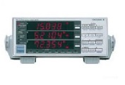
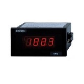
- Simultaneous display of Voltage and Frequency
- Line Supply: 100V to 130V or 200V to 260V, 47Hz to 63Hz
- Power consumption: 37VA
- Operating Temperature: 0° C to + 50°C
- Storage Temperature: -40°C to +70° C
- Safety: Designed to UL1244, IEC 348
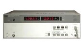
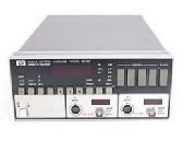
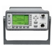
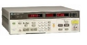
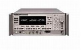
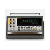
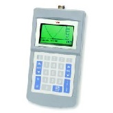
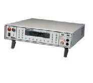
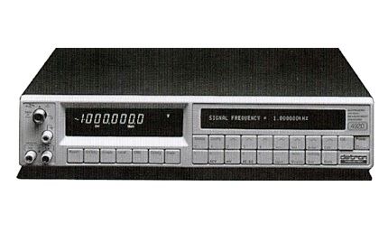
The WaveTek 4920 Alternating Voltage Measurement Standard (AVMS) is designed to replace traditional AC/DC Thermal Transfer Standards in high accuracy Alternating Voltage measurement applications. Fully traceable measurements can be made with uncertainties equal to or better than all but the most specialized standards, but with the speed, ease of use and convenience of a programmable, intelligent device. What is more, these features are all contained in one single unit, other references and instrumentation are not required for normal operation. Just connect the 4920, program the appropriate voltage range from the front panel or IEEE-488.2 interface, and just seconds later, the value of the input signal is displayed on the bright, easy to read, seven segment Vacuum Fluorescent display.
Rugged Performance
At the front end of the instrument is a proprietary attenuator design that achieves three functional aspects-long term stability, frequency flatness and input overvoltage protection. This unique design will withstand a full 1100V overload on any range without damage, while being flat to within 10ppm in the mid-band, 500ppm at 1 MHz. Significantly, this frequency flatness is not dependent on the use of gain-defining trimpots or trimcaps, so the 4920 can withstand potentially rough treatment during shipment by commercial carriers to and from the primary standards lab.
Low Cost of Ownership
For operation in Broadband mode, only three points per voltage range require calibration, 1kHz at 30% of range and 1MHz at nominal full range (lower frequencies on the 100V to 1000V ranges). In use, the frequency and approximate amplitude of the unknown input signal is determined and automatically corrected by a calibration factor derived from the range's three calibration points, which are stored in non-volatile memory.
Spot Calibration
The Broadband operating mode is the most convenient, but not the most accurate. Reduced measurement uncertainties may be achieved in "Spot Cal" mode, in which corrections for specific voltage/frequency points, additional to the Broadband calibration points, are stored in non-volatile memory. This is analogous to the more familiar technique used with AC/DC difference from a calibration certificate and manually correcting a reading. With the 4920, however, these characterizations may be switched on and off by the user, and when selected are applied automatically by the microprocessor, under front panel of IEEE-488.2 control.
AC/DC Transfer
For most applications, the 4920's performance in Broadband or Spot modes will be sufficient. However, improved long term stability and temperature performance may be achieved using the AC/DC Transfer mode, which effectively removes the effects of long term DC gain and temperature drift of the input attenuators and the 4920's internal DC reference. The user applies a known Direct Voltage to the input, first positive and then negative. The instrument then calculates the average of the two to eliminate turnover errors and compares the unknown Alternating Voltage input to this stored value. The result is displayed as a number of ppm deviation from the average of the two Direct Voltage readings. For the ultimate in measurement performance, Transfer mode may be used in conjunction with spot calibrations.
Millivolt Ranges
Calibration of the millivolt output ranges of single and multifunction calibrators has always been a difficult, time=consuming and costly process. The 4920 has simplified millivolt measurements, using a by-passable millivolt amplifier placed between the signal of interest and the calibrated higher ranges of the 4920. The gain of the amplifier at the signal frequency of interest is measured using these higher ranges, which is then used to calculate the value of the millivolt level input signal. This approach enables a level of accuracy previously attainable only through the use of specialized, expensive and time-consuming techniques.
| Manufacturer | WaveTek |
|---|---|
| Condition | Used |