The Solar Electronics LISNs use a series inductor between the test sample and the power source to provide the impedance-versus-frequency characteristic. A coaxial connector with dc isolation is provided for connection to the associated frequency selective EMI meter. The power source end of the inductor is bypassed to ground.
Due to the large current-carrying capability of some LISNs, it is not always practical to use a switch for changing inductance values. Instead, some models are equipped with a high current pin plug-and-jack combination for quickly connecting and disconnecting a network and substituting another. This nylon insulated pin plug and jack arrangement is a safety feature, well isolated from inadvertent short circuits, providing protection to operating personnel.
EMI specifications require one LISN in each ungrounded power lead. Even though the neutral is considered “ground,” if it is not connected to chassis inside the unit under test, the lead must be tested with an LISN. Therefore, use two LISNs in dc or single phase ac applications, three LISNs for delta-connected three phase circuits, and four LISNs for ‘Y’ connected three phase circuits.
Application
When measuring conducted radio interference voltages from active power lines to ground, it is essential to know the line impedance so that repeatable tests can be made by more than one laboratory. Artificial line impedances are specified in MIL-STD-462, V.D.E., C.I.S.P.R., C22.4, NACSEM 5100, ANSI C63.2 and other EMI specifications.
The characteristic impedance of the five microhenry and 50 microhenry LISNs brackets the mean value of power line impedance which has been measured by independent researchers. These two inductance values in parallel with the 50 ohms of the EMI meter fall between the minimum and maximum line impedance values which have been measured. The mean value would be represented by a twenty microhenry inductor in parallel with 100 ohms.
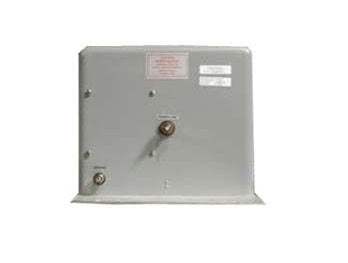
Model No
9632-50-TS-50-N
Condition
Used
Manufacturer
Solar
Current
50 A
Frequency
50 MHz
30+ Years in Business
Secure Payments
Sell Test Equipments
Knowledgeable Staff
On-site Lab
30+ Years in Business
Secure Payments
Sell Test Equipments
Knowledgeable Staff
On-site Lab
Hey👋Let's start with your email
 Chat Live
 Contact Us
 sales@valuetronics.com