


Additional Features:
- DC Output Range: Volts: -36 to +36; Amps: -1.5 to +1.5
- Current Sink: ± 0.3 A
- Ripple and Noise: <0.01% of max. power or 3 mV RMS
- Gain: >35,000V per volt
- Output Impedance: 0.005 W
- AC Input: 105 to 125 VAC or 210 to 250 VAC selectable, 45-65 Hz
- AC Source Current @ 125 VAC: 1.6 A
- Units may be connected in series for added voltage using a master/slave interconnection; they cannot be used in parallel
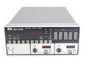
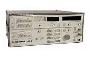
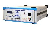
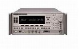
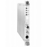
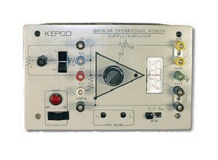
The Kepco BOP 36-1.5M is a fast, programmable Bipolar Power Supply. A fast-programmable power supply, although stable with resistive loads, may become unstable with reactive loads. The reason is the additional phase-shift introduced by a reactive load at its output. This may shift the power supply's response curve precariously close to the unity gain crossover frequency and thereby reduce the stability margin. As a result, the power supply may, with reactive loads, exhibit instability or even oscillatory behavior. For stable operation of a fast-programmable power supply, the reactive load characteristics must be a major part of the specifications for the various fast programmable models is devoted (as might be expected) to dynamics.
The Kepco BOP Series are fully rated power supplies and are also high-powered operational amplifiers with full 4-quadrant, bipolar operation. The output is capable of both sustained d-c and the replication of arbitrary a-c waveforms.
With the Kepco BOP Series, the voltage and current outputs can be controlled smoothly and linearly through the entire rated plus and minus ranges, passing smoothly through zero with no polarity switching.
Output Range
The unique character of the BOP, its ability to operate with either positive or negative output bidirec1ionally, as a source, is enhanced by its ability to function as a limited sink.
BOP is a "sink" when the polarity of its voltage does not agree with the direction of its current-it absorbs energy.
If voltage and current are plotted orthogonally quadrants I and III are the source quadrants. II and IV are sink quadrants. The operating region of a BOP is defined by the shaded portion of the output characteristic.
Control/Programming
BOP models have a front panel patch board with a built-in vernier voltage feedback rheostat and bipolar reference. Output voltage is controlled by controlling the reference potentiometer from the plus (+) to the minus (-) reference through zero. The output voltage is proportioned to the selected reference by the feedback rheostat. The patch board construction makes it easy to sum or substitute other potentials at the input and to substitute external feedback to stabilize current or such physical phenomena as heat, speed, force, or electrochemical action.
Offsets
The equivalent offset voltage and current variations for BOP are tabulated tor the effect of source changes, load, temperature, and time.
Offset Nulling
The initial or bias part of the main control channel's voltage offset and current offset can be nulled by built-in trimmers.
References
A pair of ± 6.2 V ± 5%, 1 milliampere references referred to the common/sense terminal are provided for offsetting or biasing purposes.
Gain
The open-loop dc fain is in excess of 35 volts/volt.
Current Stabilization
The BOP is equipped with a pair of built-in current-sensing and feedback arrangements for protective limiting. They are set for approximately 110% of the rated current in both directions and are not adjustable.
For the precision control of current, bidirectionally, the feedback to the main control channel can be reconfigured so as to sample the drop across an external current-sensing resistor in the common output lead.
Dynamics
Each BOP is equipped with an internal, fast/slow selector switch. The slow position restricts the bandwidth so that the BOP can drive reactive loads without restriction. The slow position is recommended for low frequency or dc application to discriminate against higher frequency pick-up noise.
Output Impedance
Expressed as a function of frequency, the output impedance is a measure of dynamic stabilization. As a voltage stabilizer, the DC and low frequency value is given by the load effect. At frequencies above the stabilizer's cutoff, the impedance increase with frequency becomes asymptotic to the tabulated characteristic series inductance. As a current stabilizer, the impedance decrease above the stabilizer's cutoff frequency becomes asymptotic to the tabulated characteristic shunt capacitance.
Distortion
For a small signal (2 volts peak-to-peak, no load), harmonic distortion is less than 0.5 %.
Bandwidth/Programming Speed
The dynamics of the BOP output may be expressed in both the time domain (as its response to a step-program) or in the frequency domain (bandwidth for large and small signals).
| Manufacturer | Kepco |
|---|---|
| Condition | Used |
| Amps | 1.5 A |
| Volts | 36 V |
| Power | 54 W |