Applications
The Yokogawa DL2700 is available in either 2, 4, or 6 or 8 input-channel models with a maximum record length of 1, 4 or 16 megawords. The printed circuit board is designed so that the oscilloscope can easily be upgraded by increasing the number of input channels and record length. The DL2700 features high waveform update rates, an intuitive, easy-to-use Zoom function, a History Memory function that allows earlier screens to be observed, a wealth of trigger functions, automatic measurement of waveform parameters, waveform computing, and so on. These features enable users to capture abnormal phenomena and analyze them smoothly and efficiently.
The front end including attenuators and preamplifiers is the same as the DL4100's and the processor system is common to both the DL5100's and AR4000's. Two new ASIC's were developed for the data acquisition stage. The front end and data acquisition stages are configured so that a single printed circuit board supports two channels for easier addition of channels. In the data acquisition stage, the acquisition memory is installed on a separate board so that record length can be changed simply by changing the type of memory board. Consequently, replacing the memory board also upgrades the record length.
Analog Stage
The DL2700 uses Yokogawa-developed preamplifiers at its front end, featuring the 150 MHz input frequency bandwidth and the direct-current accuracy of ±1.5%. The 2 mV/div maximum sensitivity is increased to 4 mV/div at the front end stage by doubling the A/D-converted data at the digital stage. The multiplexer circuitry is made up of discrete components and the circuitry alone has a bandwidth of no less than 200 MHz. The channel-to-channel isolation across the whole circuitry of the oscilloscope, including the multiplexer circuitry, is -40dB.
An 8-bit, 250 MS/s A/D converter is incorporated in every channel. The converter normally operates at 200 MS/s. In the interleave mode, however, an analog signal is multiplexed by the multiplexer circuitry so the converter operates at 250 MS/s by means of the interleave method, thus achieving a sampling rate as high as 500 MS/s.
In the trigger stage, each channel contains one comparator, while only channel 1 includes two comparators for the Window Trigger function. Channel 1 also contains the circuitry for the TV Trigger function. The TV Trigger function is compatible with the NTSC, PAL, and HDTV systems. Three digital ASIC's and one analog ASIC that were developed for DL4100 and DL5100 are used in the trigger logic circuitry.
Waveform Data Processing Stage
The waveform data processing stage consists of the primary data processing circuitry that writes A/D-converted data into the acquisition memory, the secondary data processing circuitry that performs such processes as the sorting of acquired data or peak-to-peak compression, and the acquisition and data processing memories.
This stage uses two newly developed ASIC's (CMOS gate arrays). One is responsible for performing primary data processing. The other generates various timing signals for the primary data processing, controls the memories, and performs secondary data processing, acting as an interface between respective memories and CPUs.
Primary Data Processing Stage
The primary data processing stage reduces the rate of A/D converted data to a one-fourth, performs the processes described below, and further reduces the rate to a half depending on such conditions as the Time/Div-axis settings.
This stage:
The Box Average function has been introduced in the DL series of oscilloscopes for the first time. Data that have undergone the process of this function are theoretically equivalent to those that have undergone the moving-average process and then the data density is decimated. In fact, this function takes an average of consecutive 2n data items (256 maximum) within the period of decimation and writes the average into the acquisition memory. Acquired data, which normally consist of 8 bits, are treated as 16-bit data during "box averaging." This strategy has made high-resolution measurement possible even for one-shot signals.
Secondary Data Processing Stage
As the major actions, the secondary data processing stage:
These processes are executed by means of hardware to achieve a waveform update rate of approximately 3 cycle/s for a 1-megaword/channel, 8-channel application.
Processor System
The processor system consists of two processors: Intel 80960KB that performs input control, computing and display processing, and Toshiba TMP68303 that assumes user interface communication control and so forth.
Firmware
The DL2700 succeeds the human-machine interface used in its predecessor model DL5100 for consistent operability. Functionally, it also succeeds the DL5100's features including the capability of outputting screen image data. Using the standard floppy drive and SCSI interface as well as an optional built-in magneto-optic disk drive, users can easily exchange data with a personal computer. For waveform display, the firmware has been designed to take advantage of the long-recording memory. The modes of display include simultaneous view of both the entire waveform and its partial close-up, view of partial close-up only, and view of an indicator that enable users to keep track of which part of the entire waveform they are viewing. These features have made the oscilloscope even easier to use.
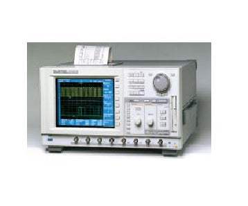
Model No
DL2700
Condition
Used
Manufacturer
Yokogawa
Channels
8
Frequency
150 MHz
Record length
160 MPts
Sampling rate
500 MS/s
30+ Years in Business
Secure Payments
Sell Test Equipments
Knowledgeable Staff
On-site Lab
30+ Years in Business
Secure Payments
Sell Test Equipments
Knowledgeable Staff
On-site Lab
Hey👋Let's start with your email
 Chat Live
 Contact Us
 sales@valuetronics.com