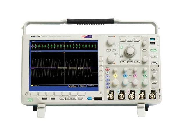
The Tektronix DPO4102B is a 1 GHz, 2 Channel Digital Oscilloscope.
With the MSO/DPO4000B Mixed Signal Oscilloscope Series, you can analyze up to 20 analog and digital signals with a single instrument to quickly find and diagnose problems in complex designs. Bandwidths up to 1 GHz and up to 5X oversampling on all channels ensure you have the performance you need to see fast-changing signal details. To capture long windows of signal activity while maintaining fine timing resolution, the MSO/DPO4000B Series offers deep record length of up to 20M points standard on all channels. And with Wave Inspector® controls for rapid waveform navigation, automated serial and parallel bus analysis, limit and mask testing, and automated power analysis – your Tektronix oscilloscope provides the feature-rich tools you need to simplify and speed debug of your complex design.
Comprehensive features speed every stage of debug
These oscilloscopes offer a robust set of features to speed every stage of debugging your design – from quickly discovering an anomaly and capturing it, to searching your waveform record for the event and analyzing its characteristics and your device’s behavior.
Discover
To debug a design problem, first, you must know it exists. Every design engineer spends time looking for problems in their design, a time-consuming and frustrating task without the right debug tools. The industry’s most complete visualization of signals provides fast insight into the real operation of your device. A fast waveform capture rate – greater than 340,000 waveforms per second with FastAcq® – enables you to see glitches and other infrequent transients within seconds, revealing the true nature of device faults. A digital phosphor display with color- and intensity-grading shows the history of a signal’s activity by using color or intensity in areas of the signal that occur more frequently, providing a visual display of just how often anomalies occur.
Capture
Discovering a device fault is only the first step. Next, you must capture the event of interest to identify the root cause. Accurately capturing any signal of interest begins with proper probing. Low capacitance probes are included with the oscilloscope, one for each analog channel. These industry-first high-impedance passive voltage probes have less than 4 pF of capacitive loading to minimize the effect of the probe on your circuit's operation, offering the performance of an active probe with the flexibility of a passive probe.
A complete set of triggers - including runt, time out, logic, pulse width/glitch, setup/hold violation, serial packet, and parallel data - help you quickly find your event. With up to a 20M point record length, you can capture many events of interest, even thousands of serial packets, in a single acquisition for further analysis while maintaining high resolution to zoom in on fine signal details.
From triggering on specific packet content to automatic decode in multiple data formats, the oscilloscope provides integrated support for the industry's broadest range of serial buses - I2C, SPI, USB, Ethernet, CAN, LIN, FlexRay, RS-232/422/485/UART, MIL-STD-1553, and I2S/LJ/RJ/TDM. The ability to decode up to four serial and/or parallel buses simultaneously means you gain insight into system-level problems quickly.
To further help troubleshoot system-level interactions in complex embedded systems, the oscilloscope offers 16 digital channels in addition to its analog channels. Since the digital channels are fully integrated into the oscilloscope, you can trigger across all input channels, automatically time correlating all analog, digital, and serial signals. The MagniVu™ high-speed acquisition on these channels enables you to acquire fine signal detail (up to 60.6 ps resolution) around the trigger point for precision timing measurements. MagniVu is essential for making accurate timing measurements for setup and hold, clock delay, signal skew, and glitch characterization.
Search
Finding your event of interest in a long waveform record can be time-consuming without the right search tools. With today’s record lengths pushing beyond a million data points, locating your event can mean scrolling through thousands of screens of signal activity.
The innovative Wave Inspector® controls give you the industry’s most comprehensive search and waveform navigation capability. These controls speed panning and zooming through your record. With a unique force feedback system, you can move from one end of your record to the other in just seconds. User marks allow you to mark any location that you may want to reference later for further investigation. Or, automatically search your record for criteria you define. Wave Inspector will instantly search your entire record, including analog, digital, and serial bus data. Along the way, it will automatically mark every occurrence of your defined event so you can quickly move between events.
Analyze
Verifying that your prototype’s performance matches simulations and meets the project’s design goals requires analyzing its behavior. Tasks can range from simple checks of rise times and pulse widths to sophisticated power loss analysis and investigation of noise sources. The oscilloscope offers a comprehensive set of integrated analysis tools including waveform- and screen-based cursors, automated measurements, advanced waveform math including arbitrary equation editing, FFT analysis, and trend plots for visually determining how a measurement is changing over time. Specialized application support for serial bus analysis, power supply design, and video design and development is also available.
Wave Inspector® navigation and search
With long record lengths, a single acquisition can include thousands of screens of waveform data. Wave Inspector®, the industry’s best tool for navigation and search, enables you to find events of interest in seconds.
Zoom and pan
A dedicated, two-tier front-panel control provides intuitive control of both zooming and panning. The inner control adjusts the zoom factor (or zoom scale); turning it clockwise activates zoom and goes to progressively higher zoom factors while turning it counterclockwise results in lower zoom factors and eventually turning zoom off. No longer do you need to navigate through multiple menus to adjust your zoom view. The outer control pans the zoom box across the waveform to quickly get to the portion of waveform you are interested in. The outer control also utilizes force-feedback to determine how fast to pan on the waveform. The farther you turn the outer control, the faster the zoom box moves. Pan direction is changed by simply turning the control the other way.
Play/Pause
A dedicated Play/Pause front-panel button scrolls the waveform across the display automatically while you look for anomalies or an event of interest. Playback speed and direction are controlled using the intuitive pan control. Once again, turning the control further makes the waveform scroll faster and changing direction is as simple as turning the control the other way.
Digital phosphor technology with FastAcq®
Digital phosphor technology with FastAcq provides you with fast insight into the real operation of your device. Its fast waveform capture rate – greater than 340,000 wfms/s – gives you a high probability of quickly seeing the infrequent problems common in digital systems: runt pulses, glitches, timing issues, and more.
To further enhance the visibility of rarely occurring events, intensity grading is used to indicate how often rare transients are occurring relative to normal signal characteristics. There are four waveform palettes available in FastAcq acquisition mode.
The Temperature palette uses color-grading to indicate the frequency of occurrence with hot colors like red/yellow indicating frequently occurring events and colder colors like blue/green indicating rarely occurring events.
The Spectral palette uses color-grading to indicate the frequency of occurrence with colder colors like blue indicating frequently occurring events and hot colors like red indicating rarely occurring events.
The Normal palette uses the default channel color (like yellow for channel one) along with gray-scale to indicate the frequency of occurrence where frequently occurring events are bright.
The Inverted palette uses the default channel color along with grayscale to indicate the frequency of occurrence where rarely occurring events are bright.
These color palettes quickly highlight the events that over time occur more often or, in the case of infrequent anomalies, occur less often. Infinite or variable persistence choices determine how long waveforms stay on the display, helping you to determine how often an anomaly is occurring.
Accurate high-speed probing
The TPP Series probes, included standard with every MSO/DPO4000B Series oscilloscope, provide up to 1 GHz of analog bandwidth, and 3.9 pF of capacitive loading. The extremely low capacitive loading minimizes adverse effects on your circuits and is more forgiving of longer ground leads. And, since the probe bandwidth matches or exceeds your oscilloscope bandwidth, you can see the high-frequency components in your signal which is critical for high-speed applications. The TPP Series passive voltage probes offer all the benefits of general-purpose probes like high dynamic range, flexible connection options, and robust mechanical design while providing the performance of active probes. In addition, a low attenuation, 2X version of the TPP probes are available for measuring low voltages. Unlike other low-attenuation passive probes, the TPP0502 has high bandwidth (500 MHz) as well as low capacitive loading (12.7 pF).
Model No
DPO4102B
Condition
Used
Manufacturer
Tektronix
Channels
2
Frequency
1 GHz
Record length
20 MPts
Sampling rate
5 GS/s
30+ Years in Business
Secure Payments
Sell Test Equipments
Knowledgeable Staff
On-site Lab
30+ Years in Business
Secure Payments
Sell Test Equipments
Knowledgeable Staff
On-site Lab
Hey👋Let's start with your email
 Chat Live
 Contact Us
 sales@valuetronics.com