


Additional Features:
- All DVB-T modes supported in line with ETSI EN 300744
- High-end demodulator
- High-end test receiver
- Standard test receiver
- SFN option
- Simple, user-friendly operation
- Modular design–easy retrofitting of options
- IEC/IEEE bus and RS-232-C interface
- MPEG-2 decoder option
Common to all models
- In-depth measurement capabilities
- Simple, user-friendly operation
- Modular design – easy retrofitting of options
- General measurement functions for: RF input level, carrier frequency offset, bit rate offset, BER (before Viterbi, before and after Reed-Solomon)
- MPEG-2 transport stream output (serial or parallel)
- Alarm messages for measurement functions, internal storage
- Seven alarm-triggered relays for switching external devices
- Integrated noise generator for measurement of noise margin
- IEC/IEEE bus and RS-232-C interface
Common Characteristics
- IF input: 50 W, BNC female, rear panel, 36 MHz
- Return loss in channel: ≥30 dB
- Level range: –30 dBm to –5 dBm
- IF output: 50 W, BNC female, rear panel, 36 MHz
- Return loss in channel: ≥20 dB
- Level, regulated: –17 dBm
- 10 MHz reference input Level range: 50 W, BNC female, rear panel; –20 dBm to +16 dBm
- 10 MHz reference output Level: 50 W, BNC female, rear panel; typ. +11 dBm
OFDM characteristics
- Bandwidth operation: 6 MHz, 7 MHz and 8 MHz, switchable
- SAW filters: 6 MHz, 7 MHz, 8 MHz or OFF
- Bit rate clock inaccuracy: <10 ppm (typ. < 3 ppm)
- FFT mode: 2K or 8K carriers
- Constellation: QPSK, 16QAM, 64QAM
- Guard interval: 1/4, 1/8, 1/16, 1/32
- Code rate: 1/2, 2/3, 3/4, 5/6, 7/8
- Hierarchical modulation: OFF, α= 1, α= 2, α= 4
- Equivalent noise degradation (END) at 64QAM; R 2/3: ≤1.5 dB
- Channel correction: self-adapting
- I/Q inversion: automatic, with indication
- BER processing: before Viterbi decoder, before and after Reed-Solomon decoder
Measurements
Level, frequency offset, bit rate offset, TS bit rate/BER (bit error ratio) before Viterbi decoder, before and after Reed-Solomon decoder/MER (modulation error ratio) in dB and %/SNR (signal-to-noise ratio), carrier suppression (2K and 8K)/quadrature error, amplitude imbalance, phase jitter/shoulder attenuation (upper/lower) in line with ETSI TR 101290/crest factor
Graphic displays
Constellation diagram, start/stop frequencies and number of symbols selectable/MER(f) in dB: RMS and max. values, start/stop frequencies selectable/MER(f) in %: RMS and min. values, start/stop frequencies selectable/Interference(f) in dB: RMS and max. values, start/stop frequencies selectable/I/Q(f), start/stop frequencies and number of symbols selectable/frequency spectrum, start/stop frequencies selectable/amplitude(f), start/stop frequencies selectable/phase(f), start/stop frequencies selectable/group delay(f), start/stop frequencies selectable/polar plot, start/stop frequencies selectable/amplitude distribution (RF)/CCDF (RF)/impulse response (t) with zoom (max. zoom = 20) SFN frequency offset (EFA-K10)/history for level (all level units available), MER (dB and %), BER before Viterbi, BER before Reed-Solomon decoder, all measurements: MAX and MIN and AVERAGE and MAXMIN detectors running in parallel
Standard test receiver (model .40)
- Selective receiver
- Typical use in the field where adjacent channels need
- to be filtered
- High-end synthesizer with low phase noise
- Excellent price/performance ratio
High-end demodulator (model .43)
- Wideband input (non-selective receiver), tunable
- Typically used for transmitter testing
- Outstanding SNR, excellent intermodulation characteristics
- High-end synthesizer with extremely low phase noise
High-end test receiver (model .43 + EFA-B3 option)
- Outstanding SNR and improved intermodulation characteristics
- Rejection of image frequency and IF
- Two additional selective RF inputs (50 W and 75 W)
- Extended frequency range from 4.5 MHz to 1000 MHz
MPEG-2 decoder (EFA-B4 option)
- Realtime analysis in line with ETSI TR 101290
- Error report
- Video and audio output
Video distributor (EFA-B6 option) *Only possible with EFA model .43 and if EFA-B4 option (MPEG-2 decoder) is fitted
- Provides four video outputs (two on
- front and two on rear panel)
6 MHz SAW filter (EFA-B11 option)
- Adjacent-channel rejection
- In line with US requirements
7 MHz SAW filter (EFA-B12 option)
- Designed in line with DVB-T standards
- Adjacent-channel rejection
- In line with European and Australian standards
8 MHz SAW filter (EFA-B13 option)
- Designed in line with DVB-T standards
- Adjacent-channel rejection
- In line with European standards
Analog and digital functions in one instrument
Using the OFDM demodulator option (EFA-B10), even analog EFA TV test receivers (models .12 and .78) and demodulators (models .33 and .89) can be upgraded to dual-mode versions: analog and digital in one unit.
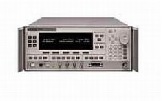
Characteristics
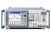
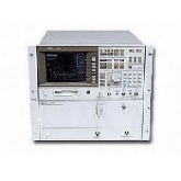
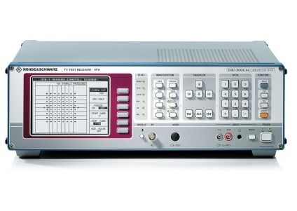
The EFA DVB-T test receiver, fully compatible with the ETSI EN 300744 standard, receives, demodulates, decodes, and analyzes OFDM (orthogonal frequency division multiplex) signals. All key parameters for demodulating the receive signal can be selected automatically or manually:
- 6 MHz, 7 MHz or 8 MHz operating bandwidth
- 2K or 8K OFDM modulation
- QPSK, 16QAM or 64QAM constellation diagram
- 1/2, 2/3, 3/4, 5/6 or 7/8 code rate
- 1/4, 1/8, 1/16 or 1/32 guard interval
- "α" = 1, 2 or 4 hierarchical demodulation
- Reed-Solomon error correction 204/188
- 6 MHz, 7 MHz or 8 MHz SAW filter bandwidth (selectable)
The operating principle of the receiver is basically the same as that of the other receivers from the EFA family, except for certain functions specified in standards.
Realtime signal analysis
The EFA’s powerful digital signal processing provides fast and thorough analysis of the received DVB-T signal. Analysis is performed simultaneously with, but independently of, demodulation and decoding. The MPEG-2 transport stream is permanently available for decoding as well as for vision and sound reproduction.
Owing to its realtime analysis capability, the high number of measured values necessary for the complex calculation and display processes are made available for subsequent mathematical/statistical processing in an extremely short, as yet unequalled, time. Because of its high speed data acquisition, the EFA test receiver is the ideal choice not only in R & D but also in production environments where short measurement cycles are essential.
Features
The EFA-T, even the basic version, features a wide range of innovative measurement functions, allowing comprehensive, in-depth signal analysis. In addition to measuring general parameters such as bit error ratio (BER), more thorough analysis includes the following:
- I/Q constellation diagrams: the number of symbols to be displayed is user-selectable, range: 1 to 999 999 symbols
- Calculation of I/Q parameters: amplitude imbalance, quadrature offset, carrier suppression, phase jitter, SNR, and MER (modulation error ratio)
- Frequency domain displays, e.g. MER(f), I|Q(f) or interferer
- Amplitude, phase and group-delay/ frequency response displays
- Amplitude spectrum, including automatic shoulder attenuation measurement in line with ETSI TR 101290
- Long-term monitoring of dedicated parameters through the history function, monitoring time selectable from 60 s to 1000 days
- Linearity analysis from amplitude distribution histogram or CCDF
- Received impulse response within and outside of the guard interval – including zoom function
- Frequency offset measurement for analysis of single frequency networks (SFN)
DVB-T: OFDM modulation for terrestrial broadcasting of digital TV signals
The DVB-T standard employs OFDM (orthogonal frequency division multiplex) modulation. This modulation is applied to the downconverter module (selective or non-selective, depending on the model) which converts the signal to a 36 MHz IF. It can then be filtered by different SAW filters (depending on the occupied bandwidth), and Gaussian noise can be internally added for margin measurements.
The IF signal is converted to the baseband using a numeric control oscillator. A fast Fourier transform (2k or 8k) translates the signal from the time domain to the frequency domain. Then, channel estimation is used to correct the signal’s amplitude, phase, and delay (continuous and discrete pilots are used for this task) to eliminate most of the degradation introduced during RF transmission.
Data packets are then applied to the Viterbi convolutional decoder, data deinterleaver (outer de-interleaver), Reed-Solomon decoder and data derandomizer (energy dispersal). Finally, the MPEG-2 interface feeds the demodulated MPEG-2 transport stream to the hardware output interface (TS SPI or TS ASI).
Typical applications
Production testing on modulators and transmitters (calibration and test)
The EFA’s analysis capabilities make it possible to pinpoint problems such as interferers and inadequate carrier suppression: The constellation diagram shows the symbols, but only if a single carrier is affected – the difficulty is localization. This is exactly what the I/Q measurement function does: Symbols are displayed as a function of carriers (frequency domain) to locate the problem in the spectrum display. Once the interferer is localized, the constellation display can be used for further evaluation. This approach can also be used with the MER-vs-frequency measurement function.
Transmitter installation and adjustment of single frequency networks (SFN)
The time domain analysis extends the EFA’s range of applications to SFN installation and adjustment – an area where spectrum and impulse-response analysis are very useful. The impulse response function makes it possible to visualize the delay between two transmitters at a reception point. This measurement function can be used to optimize the delay between the transmitters. The zoom function makes it possible to see fast echoes, for example direct reflections from a building, mountain, etc. In order to check whether all SFN transmitters operate on exactly the same frequency, the EFA can furthermore be equipped with the EFA-K10 option. Together with the impulse response function, this option makes it possible to monitor all parameters that are important for SFN operation and thus ensures correct operation.
Coverage measurements on terrestrial signals
To allow measurements to be performed under even the worst reception conditions, a single keystroke will optimize the OFDM demodulator for mobile reception (where a lot of impairments affect transmission quality) or stationary reception. The algorithms for speed and channel equalization are optimized, as is internal level control.
Monitoring TV transmitters and transposers
The EFA is the perfect solution for DVB-T signal monitoring. An alarm is triggered if one of the selected parameters exceeds the threshold that has been set. The incident level, OFDM synchronization, MER (modulation error ratio), BER (before Viterbi and before Reed-Solomon decoders), and the MPEG-2 transport stream output can be checked in realtime independent of other measurements and decoding. If an error occurs, a 1000-row register is available to record the date, time, and designation of the event. The EFA-B4 MPEG-2 decoder option extends monitoring capabilities. Realtime measurements in line with test specifications for DVB systems (ETSI TR 101290 – priorities 1, 2, and 3) can be performed and make the EFA a complete DVB-T monitoring system.
| Manufacturer | Rohde & Schwarz |
|---|---|
| Condition | Used |
| Frequency | 1 GHz |
| B11 | 6 MHz SAW filter |
|---|---|
| B12 | 7 MHz SAW filter |
| B13 | 8 MHz SAW filter |
| B3 | RF Preselection for demodulator |