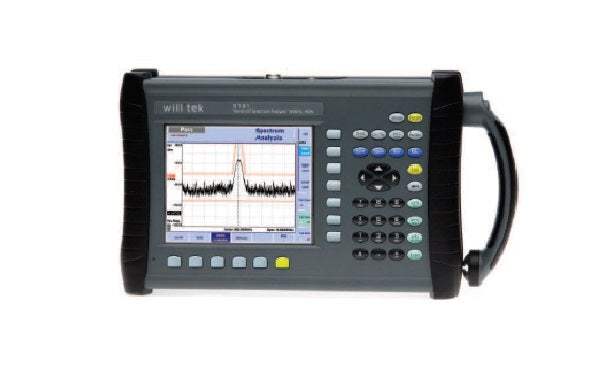
The HSA9101B Handheld Spectrum Analyzer provides RF engineers with the excellent performance of a workbench analyzer in a handheld form, at a competitive price.
One instrument for all your needs
Specifications
Frequency range
Reference frequency
Frequency counter
Frequency span
Sweep time
Resolution bandwidth (RBW)
Video bandwidth (VBW)
SSB noise
Amplitude
Measurement range
Displayed average noise level (DANL)
Input attenuation
Dynamic range
Level accuracy
RF input match
Reference level
Spurious response
Functions
Trace
Marker
Limit check
Power measurement
Demodulation
Keyboard
General
Power supply
Memory
Environmental conditions
Connectors
DC in
Serial interface
LAN (TCP/IP)
Typical measurements include transmitter testing, alignment of modulators and measuring switch breakthrough. The analyzer is fully controllable via front panel or by remote control from a PC. Measurement results and instrument settings can easily be transferred to a PC for presentation or post-processing. This rugged portable instrument is suitable for indoor and outdoor usage and with its excellent technical data and extensive feature set, meets many application needs.
Comprehensive feature set in one-button measurement
With its clear and easy-to-use operation, the HSA9101B Handheld Spectrum Analyzer presents all the measurement functions required to quickly and precisely resolve measurement tasks. The user-friendly interface with logical softkeys enhances operation.
Frequencies are increasing … needn’t break the budget
The wide frequency range from 100 kHz to 4 GHz enables testing in RF systems and modules such as modern wireless local oscillators. This frequency coverage also captures the higher harmonics from amplifier or oscillator modules, plus any spurious signals that can mix and break through into the pass-band. Its complete coverage of carrier, IF stages and audio frequencies gives the performance needed when other analyzers run out of bandwidth.
Manual or automatic control made simple
Controlling the HSA9101B from a PC is easy and convenient with the built-in RS-232 interface and Ethernet port. All functions of the spectrum analyzer can be controlled via the industrial standard remote control SCPI command set.
Convenience
No time is wasted in setting up the instrument or copying settings from one instrument to the other by hand. The 9100 Data Exchange Software, which comes with the HSA9101B, supports enhanced manage and transfer functions.
Channel systems, limit templates, settings and correction tables can easily be set up and maintained on a PC. The act of building new limit templates and correction tables is child’s play, using the PC’s mouse.
A live trace can be downloaded from the instrument at all times. An easy export to standard graphic formats such as BMP and JPG supports the need for quick documentation of measurement data. Likewise, stored traces can be uploaded to set the unit to the previous measurement settings.
Easy-to-read screens make all the difference in finding signals
The high-resolution colour VGA display (640 x 480 pixels) is great for finding misleading spurs or aligning modulators. Multiple colors facilitate the comparison of measurement traces on the screen. The extra bright 6.5” TFT display has a superb 140° viewing angle and provides fast updates.
Markers help in exactly reading signals
Up to four markers allow for exact reading of complex signals. The transmitter performance can be checked, spurious signals can be detected and sideband levels can be established using the four markers with their flexibility and clear on-screen display. By pressing Delta Marker second and third harmonic levels can easily be checked. Power level and frequency are displayed in relation to a reference point.
Pass/fail verdict with limit templates
Limit lines simplify assessment of complex displayed signals, give users the ability to decide whether the signal passes or fails. These limit templates can be set up with 30 segments.
At the same time it can be tested whether the signal exceeds an upper and/or lower limit.
Get more out of digitally modulated signals through RMS channel power measurement functions
The RMS power measurement capability offers Channel Power, Adjacent Channel Power Ratio (ACPR) and the Occupied Bandwidth (OBW). ACPR enables measurements of the leakage power from a modulated communication channel into an adjacent channel.
The occupied bandwidth measurement represents the part of the transmitted power that lies in a specified bandwidth.
This measurement function can give useful qualitative information about the used bandwidth, e.g. give useful insight into transmitter operation.
This one-button functions allow rapid measurement and information about the behaviour of the specified communication channel. All significant values are displayed at a glance.
Additionally, the channel power measurement, ACPR and OBW are implemented into the “Spectrum Analyzer Mode”. In contrast to the one-key operation an experienced user can set the measuring range, the resolution and the sweep time freely according to individual needs. This way, besides defined communication systems, measurements are easily set up when predefined communication systems cannot be used.
Accurate measurements in different RF environments
When making accurate amplitude measurements with a spectrum analyzer, it is required that any effects that alter the signal of interest between the device under test (DUT) and the analyzer be corrected while measuring. External devices like cables, amplifier, antenna and additional attenuator can influence the signal level. In the instrument software, the built-in amplitude correction is realised. The “External Device Compensation” function takes a list of frequency and amplitude pairs.
Connected linearly, these points offset the input signal accordingly. This correction table can be set up easily with the new “9100 Data Exchange Software”.
Easy adjustment onto different impedance situations
Besides the 50 ohm world, the 75 ohm impedance is common in cable TV. The new instrument software now supports this standard too. When switching between impedances the suitable correction table will automatically loaded to assure correct measurement.
AM and FM demodulation
The presence of audio signals can be checked by demodulation of AM or FM signals using Zero Span mode and listening via the built-in loudspeaker.
Digital signal processing with reloadable digital IF
RF signals are digitally processed by microprocessor and fieldprogrammable gate arrays (FPGA) to ensure both superb accuracy and repeatability as well as flexibility for future requirements.
Small and portable
With its minimal footprint, the HSA9101B is suitable for usage both on the bench and in the field. The low weight makes it a highly portable instrument in the lab and supports mobile applications in the field that seemed impossible before.
With the Willtek 1500 Battery Charger, additional battery modules can be recharged outside of the HSA9101B. The batteries are easy to exchange, preparing the instrument for many hours of independent operation in the field.
Model No
HSA9101B
Condition
Used
Manufacturer
Willtek
Frequency
4 GHz
30+ Years in Business
Secure Payments
Sell Test Equipments
Knowledgeable Staff
On-site Lab
30+ Years in Business
Secure Payments
Sell Test Equipments
Knowledgeable Staff
On-site Lab
Hey👋Let's start with your email
 Chat Live
 Contact Us
 sales@valuetronics.com