Specifications
Vertical Sensitivity
Trigger
Ext Trigger
Horizontal
X-Y MODE
Cursors and Measurement
Control Panel Function
Display System
Interface
Spectrum Analyzer Specifications
AWG Specifications
Frequency Response Analysis
Power Source Miscellaneous
The Instek MDO-2000E series is multi-functional mixed domain oscilloscope. The series includes two feature combinations: MDO-2000EG and MDO-2000EX. MDO-2000EG models have a built-in spectrum analyzer and a dual channel 25MHz arbitrary waveform generator and MDO-2000EX models feature a built-in a spectrum analyzer, arbitrary waveform generator, a 5,000 count DMM, and a 5V/1A power supply. The first of its kind, MDO-2000EX is the only oscilloscope to equip with a DMM and a power supply in the T&M industry.
While entering the spectrum mode, MDO-2000E series will display a full screen of frequency domain. Users can input Center frequency, Span, Start frequency, and Stop frequency based upon test requirements so as to rapidly and intuitively observe required frequency range that allows users to experience the user interface of a real spectrum analyzer. While observing frequency domain display, engineers can observe waveform characteristics, which are not easily to be seen from time domain waveforms, for instance, the harmonic composition of a waveform and the frequency characteristics of a modulation signal. Compared with oscilloscope' FFT, MDO-2000E series allows engineers to effectively conduct signal measurements on frequency domain.
Conventional DSO's FFT always calculates the entire signal bandwidth up to half the sampling rate (Fs). However, the insufficient calculation capability can't conduct FFT calculation with more points. Users can't have the signal's detailed frequency information due to the insufficient frequency resolution from the calculation result. Whereas MDO-2000E series analyzes signal spectrum of interest. Compared with oscilloscope FFT, MDO-2000E series allows engineers to effectively conduct signal measurements on frequency domain.
MDO-2000E series frequency domain also includes Spectrum Trace Type settings (Normal, Max-hold, Min-hold, and Average). Users can freely select various Spectrum Traces for simultaneous display. Detection method (Sample, +Peak, -Peak, and Average) can be individually set for each Trace. Additionally, users, via Cursor, can manually mark the corresponding positions to reflect Frequency and Amplitude. The Search function can also be applied to log spectrum's Peak Table. Amplitude is displayed with dB and Marker can obtain measurement data. Users can use the Search function to search and mark the amplitude and frequency of spectrum signal. Search methods include Max. peak and threshold. Measurement results can be displayed and saved.
Compared with the general spectrum analyzer, the spectrum function of MDO-2000E series can test below~9kHz signals, which is applicable to the frequency domain analysis of audio frequency and vibration. MDO-2000E series can also test the frequency domain signal with DC component without damaging the instrument. With respect to frequency domain waveform display, MDO-2000E series, featuring the same capability of a real-time spectrum analyzer, is faster than the general spectrum analyzer. Why? It is because MDO- 2000E series utilizes digital circuit and software to calculate FFT. The general spectrum analyzer can only process the signal of a narrow frequency bandwidth at a time by frequency sweeping. Each sweeping will take several ms to dozens of ms. Hundreds and thousands of frequency sweepings are gathered to form a spectrum. Therefore, the displayed spectrum is not obtained at the same time. MDO-2000E series obtains spectrum display at the same time by utilizing digital circuit and software to calculate FFT that is faster than the frequency sweeping method. The FFT settings of oscilloscopes are based upon horizontal scale (sample rate) setting, which is totally different from the frequency range setting of MDO-2000E series. Most instruments will have insufficient frequency resolution due to insufficient FFT points while conducting spectrum measurement by FFT. Compared with the FFT of oscilloscopes, MDO-2000E series satisfies users with signal measurement requirements under 9kHz; a better setting interface, measurement resolution and measurements speed.
Three screen displays on the right show the spectrum results of MDO-2000E's spectrum analyzer and the FFT of two different branded oscilloscopes after testing the same FSK signal. The parameters of FSK signal: 500mVpp sine wave, fmax: 10.2MHz, fmin: 10.0MHz, bit rate: 10.0kHz. The upper right screen display is the spectrum of MDO-2000E's spectrum analyzer. Users can directly input Center and Span Frequency by an intuitive and swift setting. Fmax and fmin can be clearly identified from the screen display.
The right screen display is an often seen spectrum from a general oscilloscope's FFT. The left boundary started from DC (low frequency signal) and the maximum frequency on the right is half of the sample rate (can be extended to the right or even out of the boundary). The Span setting for spectrum can only be switched by fixed 1-2-5 multiplying factors. Therefore, users can't set Span according to their requirements that is extremely inconvenient for the operation. In fact, switching multiplying factor is to conduct Zoom In/Out calculation on the original FFT spectrum and the sample rate remains the same during the calculation process. Users can easily encounter the upper and lower boundary limits that is totally different from the general spectrum analyzer in terms of operational experience. Most importantly, no matter how setting is changed the important fmax and fmin of spectrum can't be identified.
The right screen display is the FFT spectrum from a well-known oscilloscope manufacturer. It also provides Span setting (adjustable 1-2-5 multiplying factor) but the result is the same as the previous case, which only conducts Zoom In/Out calculation on FFT spectrum and FFT calculation points have not increased. This method is absolutely unhelpful on increasing frequency resolution. Therefore, its fmax and fmin can't be identified as well.
Users will see fmax and fmin appearing on the screen alternatively if the conventional swept tuned spectrum analyzer is used to conduct the measurement on the previous signal. The reason is that each frequency component is not obtained at the same time frame and it will take a longer time to process.
MDO-2000E also provide the frequency response analysis function (Bode plot). The FRA software can be directly downloaded from GW Instek website. Via arbitrary waveform generator, oscilloscope, and FRA software, users can obtain DUT's FRA characteristic curve plot. FRA has a very wide application range, including product circuit and component performance verification and analysis such as Feedback of Circuit Design, Filter Design, Amplifier Design, Resonant Circuit Design, Cable Frequency Response, and Signal Transformer Performance. Via FRA, users can preliminarily verify product and analyze component's characteristics without the expensive instrument.
The frequency range of FRA is from 20Hz to 25MHz; the number of test point can be selected from 10 to 90 points per decade. After completing the Bode plot, users can select measurement curve by Cursor so as to retrieve each point's amplitude and phase on the curve.
Other than the new functionalities, the hardware characteristics of MDO-2000EG and MDO-2000EX are identical to those of GDS-2000E Series. MDO-2000EG and MDO-2000EX are equipped with 8-inch display and feature bandwidth selections of 200MHz, 100MHz, and 70MHz. Models with two analog channels provide 1GSa/s real-time sampling rate per channel; models with four analog channels provide 1GSa/s maximum real-time sampling rate. The waveform update rate of 120,000 wfm/s and the minimum 1mV/div vertical range allow MDO-2000EG series MDO-2000EX to measure complex feeble signals and clearly display measurement results. With respect to the memory depth, MDO-2000E series provide 10M long memory for users to completely retrieve and analyze waveforms.
Users, based upon the application requirements, can select 1k, 10k, 100k, 1M or 10M memory depth. The segmented memory can be divided the maximum into 29,000 sections for users to bypass any unimportant waveforms so as to swiftly search all required waveforms. With the function, more meaningful waveforms can be saved and target waveforms can be displayed rapidly. With the waveform search function, users can rapidly search desired waveforms according to the required trigger conditions. MDO-2000E series also provides 1M FFT display that allows users to correctly and efficiently acquire measurement results of the frequency domain. MDO-2000E series, enhancing by the high waveform update rate of 120,000wfm/sec, Window Zoom and Peak Search, becomes the optimal choice of the economical and multi-function mixed domain oscilloscope.
120,000wfm/s Waveform Update Rate and VPO Waveform Display Technology
The MDO-2000E series oscilloscope allows users to easily and completely observe inrush signals and rare transient waveforms to increase waveform debugging efficiency by using features, including advanced VPO (Visual Persistence Oscilloscope) signal processing technology, waveform update rate as high as 120,000 wfm/s, and multi-layered afterglow display to enhance waveform display efficiency. Oscilloscope with VPO technology displays signals with three dimensional waveforms constructed by amplitude, time and signal strength to show each waveform point. 256 color gradients yield clear waveform changes. Comparing with the conventional digital storage oscilloscope, the MDO-2000E series provides more natural and more genuine signal display effect which is very close to the original analog signal.
Support I²C, SPI, UART, CAN, LIN BUS Trigger and Decoding Functions
The serial bus technology has been widely applied in the present embedded application design. The IoT devices connecting sensors and the peripheral components are using serial bus such as UART, I²C, and SPI. To rapidly and correctly trigger and analyze serial bus 2 data has posed a difficult challenge to engineers. The MDO-2000E series provides serial bus analysis function with 10M long memory depth. Users can trigger, decode, and analyze frequently used I²C, SPI and UART serial bus and CAN/LIN bus, which is often used by automotive communications.
Waveform Search Function
Users can rapidly search desired waveforms according to the trigger condition. After activating the search function, hollow inverted triangles will show the location met the trigger condition. The upper left hand corner Overall will show the total number of waveforms met the trigger condition. Users can set waveform search by the trigger condition such as Edge, pulse width, Runt, Rise/Fall, and Bus. When the trigger condition is met, hollow inverted triangles will appear. Users can save all marks to compare with the next input signal. The front panel of the MDO-2000E series controls waveform zoom-out and play/pause function to swiftly identify each desired event. The function allows users to conveniently complete waveform search and save marks for rapid comparison and analysis.
Data Log Function
Users, via the data log function, can observe waveform changes in long periods of time to ensure product reliability or measure sporadically appeared signals. The data log function, based on the requirements, can set record time and interval. Record time can be selected from 5 minutes to 1000 hours, and record interval is 5 seconds, the minimum. Waveform type for record data and CSV file format for each channel can also be selected. Data can be stored in USB drive, the MDO-2000E series or the remote computer via LAN.
Segmented Memory Function
Users Can Select “Analyze Segments” to Conveniently Obtain The Analysis Results
To achieve the most ideal application for memory depth, the MDO-2000E series has the built-in segmented memory function. The segmented memory function allows users to select the desired important signals for observation. Hence, insignificant signals can be neglected and serial bus decoding; pulse or inrush signals can be identified when retrieving signals. The segmented memory function of the MDO-2000E series allows users to select the number of sections. The maximum sections can be selected are 29,000. After activating the function, users can select and observe waveform for each segment by turning the Variable knob. The ultimate application of memory depth, therefore, is completely realized.
Mask Function
The MDO-2000E series provides the Mask function, which allows users to apply Auto Mask and user-defined Mask to determine whether the quality of the product meets the regulation. Via userdefined mask, users can set up to 8 areas and each area is up to 10 points to meet test requirements. Users can also refer to the examples from user manual to edit Mask by the PC to satisfy all test needs. By setting Save On, users can log and monitor signals, which violate test conditions.
25MHz Dual Channel Arbitrary Waveform Generator
The MDO-2000E series provides the Mask function, which allows users to apply Auto Mask and user-defined Mask to determine whether the quality of the product meets the regulation. Via userdefined mask, users can set up to 8 areas and each area is up to 10 points to meet test requirements. Users can also refer to the examples from user manual to edit Mask by the PC to satisfy all test needs. By setting Save On, users can log and monitor signals, which violate test conditions.
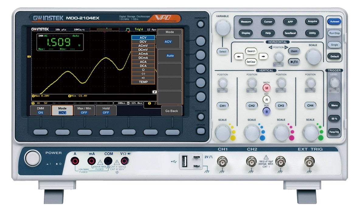
Power Supply and DMM Functions (MDO-2000ex only)
MDO-2000EX has expanded its capabilities by incorporating a 5,000 count DMM and a 5V/1A power supply. DMM provides tests for ACV, DCV, ACA, DCA resistance, diode and temperature. The highly accurate DMM can strengthen DSO's capabilities of voltage and current measurement accuracy. Power supply provides 5V/1A; 0.1V incremental adjustment which can supply power for the development board and IoT (Internet of Things) module of the often used 8051/Arduino/ESP8266/MSP430 in Microprocessors and Micro controllers experiment courses. For education and digital circuit tests, it can satisfy the voltage input requirements of 5V or 3.3V. Each increment is 0.1V and over load protection is available.
Model No
MDO-2104EX
Condition
New
Manufacturer
Instek
Channels
4
Frequency
100 MHz
Record length
10 MPts
Sampling rate
1 GS/s

30+ Years in Business
Secure Payments
Sell Test Equipments
Knowledgeable Staff
On-site Lab
30+ Years in Business
Secure Payments
Sell Test Equipments
Knowledgeable Staff
On-site Lab
Hey👋Let's start with your email
 Chat Live
 Contact Us
 sales@valuetronics.com