🎓 Request a Quote To Get An EDU Discount
Couldn't load pickup availability
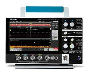
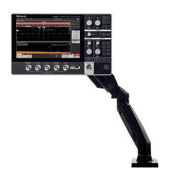
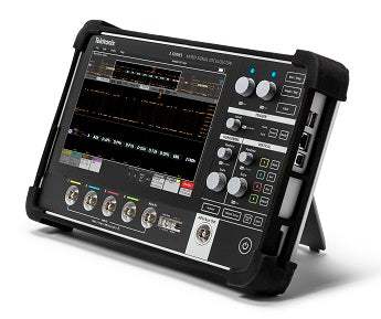
In summary, the Tektronix MSO24 configured at 200 MHz is a 4-analog-channel mixed signal oscilloscope from the Tektronix 2 Series MSO family, designed as a compact, portable instrument that works on the bench, in the field with the optional battery pack, or rack-mounted using the VESA 100 mm interface. It pairs a 10.1-inch capacitive multi-touch WXGA display with a streamlined front panel of color-coded LED-ring knobs, and shares the user interface and SCPI command set of the Tektronix 3/4/5/6 Series oscilloscopes.
The MSO24 at 200 MHz is used for daily electronics debug, embedded system development, serial-bus protocol decode, mixed-signal capture across up to 16 optional digital inputs, and field measurements where AC power is not available. With 4 analog channels and 200 MHz, it covers general debug, low- to mid-frequency digital design, and power electronics work; the higher-bandwidth members of the family (up to 500 MHz) address faster digital edges and tighter rise-time requirements.
By the 5× bandwidth-to-signal rule that Tektronix and the broader oscilloscope industry use for accurate waveform reconstruction, 200 MHz of analog bandwidth is matched to signals with fundamentals up to roughly 40 MHz. The 2.5 GS/s half-channel sample rate (10× oversampling at 250 MHz, 5× at 500 MHz) provides ample margin for sin(x)/x waveform reconstruction within the bandwidth limit. The 10 M points per-channel record length supports long captures at full sample rate — useful for protocol traces, glitch hunts, and capturing rarely occurring events with the Act-on-Event automation.
On the measurement side, the MSO24 provides 36 automated measurements with an unlimited number of measurement badges, statistics (mean, standard deviation, max, min, population), gating (screen, cursors, logic, search, time), basic and advanced waveform math (including arbitrary equation editing), and FFT with eight window functions (Hanning, rectangular, Hamming, Blackman-Harris, flattop2, gaussian, kaiser-bessel, and tekexp). Input impedance is 1 MΩ ± 1% with 14 pF ± 3 pF at the BNC, dropping to < 12 pF at the TPP0200 probe tip and < 8 pF at the P6139B probe tip. Maximum input voltage is 300 VRMS CAT II with peaks < ±425 V.
The 2 Series MSO platform is built by Tektronix, the most recognized oscilloscope brand in the global electronics industry. The instrument is CE marked for the European Union, UL approved for the USA and Canada, and RoHS compliant. Tektronix is registered to ISO 9001 and ISO 14001 by SRI Quality System Registrar. The MSO24 ships with a calibration certificate documenting traceability to National Metrology Institute(s) and ISO 9001 / ISO 17025 quality system registration, and is backed by a one-year standard warranty.
| Item | Description |
|---|---|
| TPP0200 passive voltage probe | 200 MHz, 10:1 attenuation, BNC interface — one per analog channel (4 total) |
| Instrument stand | Adjustable rear stand |
| Installation and safety manual | Translated in English, Japanese, and Simplified Chinese |
| Embedded help | Integrated on-instrument help system |
| External power supply | 24 V DC, 2.71 A AC adapter |
| Calibration certificate | Documenting traceability to National Metrology Institute(s) and ISO 9001 / ISO 17025 quality system registration |
| Warranty | One-year standard, covering all parts and labor on the instrument; one-year on included probes |
The 2 Series MSO is a compact, portable, optionally battery-operated mixed signal oscilloscope. It shares a user interface, programmatic command set, and analysis feature set with the 3 / 4 / 5 / 6 Series Tektronix oscilloscopes. A compatibility mode emulates the SCPI of the legacy TDS2000, TBS1000, and MSO/DPO2000 families — useful when replacing an older Tektronix scope in an existing automated test system.
Stacked display mode gives each waveform its own graticule slice across the full ADC range, eliminating the overlap-versus-accuracy tradeoff of a single graticule. Bus waveforms time-correlate decoded serial packets with all displayed signals, and a bus decode results table lists every packet in the acquisition with columns per protocol component.
| Model | Analog Channels | Available Bandwidths | Max Sample Rate | Record Length | Digital Channels |
|---|---|---|---|---|---|
| MSO22 | 2 | 70 / 100 / 200 / 350 / 500 MHz | 2.5 GS/s half / 1.25 GS/s all | 10 M points | 16 (optional) |
| MSO24 | 4 | 70 / 100 / 200 / 350 / 500 MHz | 2.5 GS/s half / 1.25 GS/s all | 10 M points | 16 (optional) |
| Parameter | Value |
|---|---|
| Bandwidth limits (limited by instrument BW) | 20 MHz, 70 MHz, 100 MHz, 200 MHz, 350 MHz, 500 MHz |
| Input coupling | AC, DC |
| Input impedance — BNC | 1 MΩ ± 1%, 14 pF ± 3 pF |
| Input impedance — TPP0200 probe tip | 10 MΩ, < 12 pF |
| Input impedance — P6139B probe tip | 10 MΩ, < 8 pF |
| Input sensitivity range | 1 mV/div to 10 V/div |
| Vertical resolution | 8 bit (up to 16 bit in high-resolution mode) |
| Maximum input voltage | 300 VRMS CAT II with peaks < ±425 V (derated above 4.5 MHz) |
| DC gain accuracy | ±3%, derated 0.10%/°C above 30 °C |
| Channel-to-channel isolation | 100:1 at ≤100 MHz; 30:1 above 100 MHz |
| Offset range | ±1 V (1–63.8 mV/div); ±10 V (63.9–999.5 mV/div); ±100 V (1–10 V/div) |
Note: per the manufacturer datasheet, 500 MHz bandwidth is guaranteed from 4 mV/div to 10 V/div on 500-MHz configurations.
| Parameter | Value |
|---|---|
| Time base range | 2 ns/div to 1000 s/div (all channels); 1 ns/div to 1000 s/div (half channel) |
| Time base delay range | −10 divisions to 5000 s |
| Channel-to-channel deskew range | −95 ns to +95 ns |
| Time base accuracy | ±25 ppm over any ≥1 ms interval |
| Trigger modes | Auto, Normal, Single |
| Trigger holdoff range | 0 s to 10 s |
| Trigger types (standard) | Edge, Pulse Width, Runt, Timeout, Logic, Setup & Hold, Rise/Fall Time, Parallel Bus |
| Trigger sensitivity (edge, DC coupled) | Analog input: the greater of 6 mV or 0.8 div; Aux In: 500 mVpp to 250 MHz |
| Trigger level ranges | Any input channel: ±5 divisions from center of screen; Aux In: ±8 V |
With the 2-SERIAL or 2-ULTIMATE option, the MSO24 supports trigger, decode, and analysis on I²C (to 10 Mb/s), SPI (to 20 Mb/s), RS-232/422/485/UART (to 15 Mb/s), CAN (to 1 Mb/s), CAN FD, LIN (to 1 Mb/s, with wakeup/sleep frames), and SENT.
The optional 2-SOURCE (or 2-ULTIMATE) bundle enables a built-in 50 MHz arbitrary function generator multiplexed onto the AFG/Aux Out BNC. Waveform types: Arbitrary (128k record), Sine (to 50 MHz), Square, Pulse, Ramp, Triangle, DC Level, Gaussian, Lorentz, Exponential rise/fall, Sin(x)/x, Random Noise, Haversine, and Cardiac. DC offset range is ±2.5 V into Hi-Z and ±1.25 V into 50 Ω.
| Interface | Detail |
|---|---|
| Display | 10.1-inch LCD capacitive multi-touch, 1280 × 800 (WXGA); Overlay or Stacked display modes |
| USB | Two USB 2.0 host ports; one USB device port (USBTMC) |
| Ethernet | One port, 10/100 Mb/s (and 1000 Mbps in full duplex) |
| Aux Out / Aux In | Front-panel BNC (multiplexed with AFG out); Aux In 300 VRMS CAT II |
| Probe compensation | 0 to 2.5 V at 1 kHz, source impedance 1 kΩ |
| Security / mounting / ground | Kensington-style lock; VESA MIS-D 100 mm × 100 mm; ground lug for battery operation |
The optional 2-BP battery pack provides two battery slots with hot-swap. Typical usage with dual TEKBAT-01 (Li-Ion, 14.52 VDC, 6700 mAh nominal) is up to 8 hours; single-battery is up to 4 hours. Batteries charge from AC power on the instrument or from the standalone TEKCHG-01 external charger. Charge: 0 to +45 °C; discharge: −20 to +60 °C.
| Parameter | Value |
|---|---|
| Dimensions (instrument only) | Height 210 mm (8.26 in), Width 344 mm (13.54 in), Depth 40.4 mm (1.59 in) |
| Dimensions (with battery pack) | Height 210 mm, Width 344 mm, Depth 78 mm (3.07 in) |
| Weight (instrument only) | 1.8 kg (4 lbs) |
| Weight (with one / two batteries) | 3.2 kg / 3.6 kg (7 / 8 lbs) |
| Rackmount configuration | 5U (with optional 2-RK rack mount kit) |
| Line power | 100 to 240 V ±10% at 50 Hz to 60 Hz |
| AC adapter output | 24 V DC, 2.71 A |
| Power consumption | 60 W (max) |
| Operating temperature | 0 °C to +50 °C (+32 °F to 120 °F) |
| Operating humidity | 5% to 90% RH at up to +30 °C; 5% to 60% RH above +30 °C up to +50 °C |
| Operating altitude | Up to 3,000 meters (9,842 feet) |
| Regulatory | CE marked (EU); UL approved (USA, Canada); RoHS compliant |
Native integration with TekDrive enables save and recall of waveforms, setups, and screenshots directly to a shared cloud workspace. VNC supports remote viewing and control over a network connection. An IVI driver supports LabVIEW, LabWindows/CVI, Microsoft .NET, MATLAB, and Python / C via VISA. TekScope PC analysis software extends offline analysis to saved data.
Passive voltage probes: TPP0100, TPP0200, P2221, P5050B, P6139B, P6101B, P3010, THP0301. Current probes: TCPA300 amplifier with TCP312A / TCP305A / TCP303 heads; TCPA400 with TCP404XL; TCP2020; A622; P6021A; P6022; TRCP3000; TRCP0600; TRCP0300; CT1; CT2; CT6. High-voltage single-ended probes: P5100A, P6015A, P5122, P5150. High-voltage differential: P5200A (50 MHz, 50:1/500:1). Digital: P6316 (16-channel for MSO functionality). Other: 2-BP battery pack, TEKBAT-01 spare battery, TEKCHG-01 standalone charger, 2-RK rack-mount kit, 2-PC carrying bag, 2-HC hard case, and 119-9725-00 additional AC/DC power supply.
Analog bandwidth is field-upgradable via license keys on MSO22 and MSO24 (e.g., SUP2-BW70T500-2 takes a 2-channel from 70 MHz to 500 MHz). Functionality bundles: 2-SOURCE (AFG), 2-SERIAL (I²C, SPI, UART, CAN, CAN-FD, SENT, LIN trigger/decode/analysis), and 2-ULTIMATE (2-SOURCE + 2-SERIAL). TekScope and TekDrive software subscriptions extend collaboration and offline analysis.
Important Note — AFG / Aux Out Multiplexing
The arbitrary function generator output is multiplexed with the front-panel Aux Out BNC. When the AFG is active, the Aux Out trigger-related signal is not simultaneously available. Plan accordingly for setups that depend on both signals at the same time.
This webpage was written by a human with an A.I. “Intern,” which may contain errors. Please review the Manufacturer’s Data Sheet to verify published specifications. Feedback on this webpage is always welcome — please reach out to your Test Architect at any time for questions or concerns. Thank you, we truly appreciate you being our customer.
Model No
Tektronix
Condition
New
Manufacturer
Tektronix
2-BP
Battery pack with 2 battery slots and 1 battery for use with 2 Series MSO (ships separately)
2-MSO
16 Channel Digital Probe
2-SERIAL
I 2C , SPI , UART , CAN , CAN-FD , SENT , LIN serial trigger and analysis
2-SOURCE
AFG (Arbitrary Function Generator)
2-ULTIMATE
2-SOURCE , 2-SERIAL
MSO24 2-P6139B
Adds 4 x 500 MHz , 10x probes
MSO24 R3
Standard warranty extended to 3 years
MSO24 R5
Standard warranty extended to 5 years

30+ Years in Business
Secure Payments
Sell Test Equipments
Knowledgeable Staff
On-site Lab
30+ Years in Business
Secure Payments
Sell Test Equipments
Knowledgeable Staff
On-site Lab
Request A Quote
 Chat Live
 Contact Us
 sales@valuetronics.com


