


Additional Features:
- Bandwidth: 1 GHz
- Channels: 4 Analog + 16 Digital
- Sample Rate: 5 GS/s
- Record Length: 10 MPts
- 50,000 wfm/s Maximum Waveform Capture Rate
- Suite of Advanced Triggers
- Wave Inspector® Controls Provide Unprecedented Efficiency in Waveform Analysis
- 10.4 in. (264 mm) XGA Color Display
- Small Footprint and Lightweight
- USB and CompactFlash on Front Panel for Quick and Easy Storage
- USB Plug-and-Play PC Connectivity
- TekVPI® Probe Interface Supports Active, Differential, and Current Probes for Automatic Scaling and Units
- Serial Triggering, Decode, and Analysis Options for I2C, SPI, RS-232/422/485/UART, I2S/LJ/RJ/TDM, CAN, LIN, and FlexRay
Mixed Signal Design and Analysis
- Parallel Bus Trigger and Analysis
- MagniVu™ 60.6 ps Technology Provides Finer Timing Resolution
- Per-channel Threshold Settings
- Multichannel Setup and Hold Triggering
- Next-generation Digital Waveform Display
Applications:
- Embedded Design and Debug
- Mixed Signal Design and Debug
- Investigation of Transient Phenomena
- Power Measurements
- Video Design and Debug
- Automotive Electronics Design and Debug
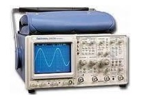
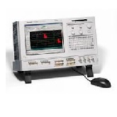
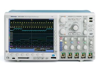
The MSO4104 provides all the features and benefits of the DPO4104, but adds 16 integrated digital channels, enabling you to visualize and correlate analog and digital signals on a single instrument. This integration extends triggering functionality across all 20 channels providing pattern and state triggering ideal for debugging mixed analog and digital designs.
Designed to Make Your Work Easier
As design complexity increases, you need tools that help you find problems quickly.
Easy to Setup and Use
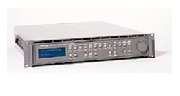
The MSO/DPO4000 Series has a large 10.4 inch XGA display, a clean front panel with familiar knobs - all in a package that is only 5.4 in. deep and weighs only 11 lb. With USB plug-and-play operation and PC connectivity, acquiring data and measurements from the instrument is as simple as connecting a USB cable from the oscilloscope to the PC.
Provided applications include NI LabVIEW SignalExpress™ Tektronix Edition LE, OpenChoice® Desktop and Microsoft Excel and Word toolbars enabling fast and easy direct communication with your Windows PC. USB and CompactFlash ports on the front panel enable simple transfer of screenshots, instrument settings, and waveform data in the palm of your hand.
When it comes to mixed signal design and debug, you want your instrument to be intuitive so you can start solving problems quickly. The MSO4000 Series drives like an oscilloscope, the tool you already know how to use. You do not have to relearn how to use the instrument every time you turn it on.
Wave Inspector® Navigation
Record length, one of the key specifications of an oscilloscope, is the number of samples it can digitize and store in a single acquisition. The longer the record length, the longer the time window you can capture with high timing resolution (high sample rate).
The first digital oscilloscopes could capture and store only 500 points, which made it very difficult to acquire all relevant information around the event being investigated. Over the years, oscilloscope manufacturers have provided longer and longer record lengths to meet market demands for long capture windows with high resolution, to the point that most mid-range oscilloscopes either come standard with, or can be optionally upgraded to, multi-megapoint record lengths. These megapoint record lengths often represent thousands of screens worth of signal activity. While standard record lengths have increased greatly over the years and can now satisfy the vast majority of applications in the marketplace, tools for effectively and efficiently viewing, navigating, and analyzing long record length acquisitions have been sorely neglected until now.
The MSO/DPO4000 Series redefines expectations for working with long record lengths with the following innovative Wave Inspector controls:
Zoom/Pan
A dedicated, two-tier front-panel knob provides intuitive control of both zooming and panning. The inner knob adjusts the zoom factor (or zoom scale); turning it clockwise activates zoom and goes to progressively higher zoom factors, while turning it counterclockwise results in lower zoom factors and eventually turning zoom off. The outer knob pans the zoom box across the waveform to quickly get to the portion of the waveform you are interested in. The outer knob also utilizes force-feedback to determine how fast to pan on the waveform. The farther you turn the outer knob, the faster the zoom box moves. Pan direction is changed by simply turning the knob the other way. No longer do you need to navigate through multiple menus to adjust your zoom view.
Play/Pause
A dedicated play/pause button on the front panel scrolls the waveform across the display automatically while you look for anomalies or an event of interest. Playback speed and direction are controlled using the intuitive pan knob. Once again, turning the knob further makes the waveform scroll faster and changing direction is as simple as turning the knob the other way.
User Marks
See something interesting on your waveform? Press the Set Mark button on the front panel to leave one or more “bookmarks” on the waveform. Navigating between marks is as simple as pressing the Previous (←) and Next (→) buttons on the front panel.
Search Marks
Don’t want to take the time to inspect the entire acquisition to find the event you’re looking for? The MSO/DPO4000 Series features a robust waveform search feature that allows you to search through your long acquisition based on user-defined criteria. All occurrences of the event are highlighted with search marks and are easily navigated to, using the front panel Previous (←) and Next (→) buttons. Search types include edge, pulse width, runt, logic, setup and hold, rise/fall time and parallel, I2C, SPI, RS-232/422/485/UART, I2S/LJ/RJ/TDM, CAN, LIN, and FlexRay packet content.
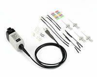
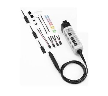
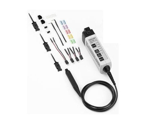
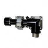
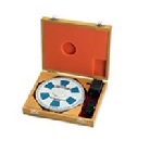
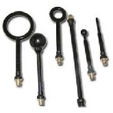
P6516 MSO Probe
This unique probe design offers two eight-channel pods. Each channel ends with a new probe tip design that includes a recessed ground for simplified connection to the device-under-test. This sleek new probe simplifies the process of connecting to the device-under-test. The coax on the first channel of each pod is colored blue making it easy to identify. The common ground uses an automotive style connector making it easy to create custom grounds for connecting to the device-under-test. When connecting to square pins, the P6516 has an adapter that attaches to the probe head extending the probe ground flush with the probe tip so you can attach to a header. The P6516 offers outstanding electrical characteristics applying only 3 pF of loading
The Power to Solve Problems Quickly
The Performance and Feature Set You Expect
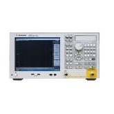
The MSO/DPO4000 Series Digital Phosphor Oscilloscopes (DPO) deliver the performance you need to visualize even your most demanding signals. Bandwidths range from 350 MHz to 1 GHz, and with all models offering a minimum of 5x oversampling on all channels and sin(x)/x interpolation standard, you can be confident that even the fastest transient events will be captured and displayed accurately. The standard 10 M record length on all channels enables you to capture long windows of signal activity while maintaining fine timing resolution.
The MSO/DPO4000 Series offers a variety of analytical solutions including cursors, 29 automatic measurements, statistics, and waveform math. Despite a tiny footprint (only 5.4 in. deep) and lightweight (11 lb.), the MSO/DPO4000 Series offers exceptional performance, a large 10.4 in. XGA display and knob-per-channel vertical controls.
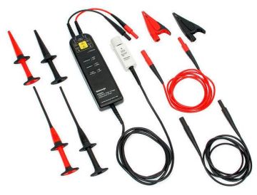
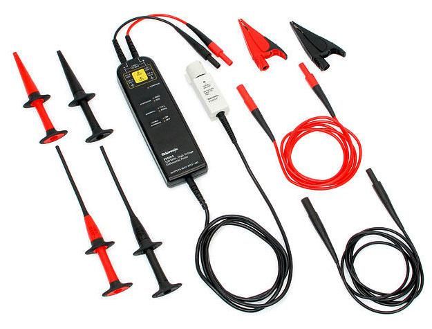
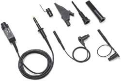
The TekVPI™ probe interface sets the standard for ease of use in probing. TekVPI probes feature status indicators and controls, as well as a probe menu button right on the comp box itself. This button brings up a probe menu on the oscilloscope display with all relevant settings and controls for the probe. The TekVPI interface utilizes a new probe power management architecture enabling direct attachment of current probes without requiring a separate, bulky power supply. Finally, TekVPI probes can be controlled remotely using USB, GPIB, or Ethernet, enabling more versatile solutions in ATE environments.
MagniVu™
The main digital acquisition mode on the MSO4000 Series will capture up to 10 M points at 500 MS/s (2 ns resolution). In addition to the main record, the MSO4000 Series provides an ultra high-resolution mode called MagniVu which acquires 10,000 points at up to 16.5 GS/s (60.6 ps resolution). Both main and MagniVu waveforms are acquired on every trigger and can be switched between at any time, running or stopped. MagniVu provides finer timing resolution than any other MSO on the market, instilling confidence when making critical timing measurements on digital waveforms.
Serial Triggering and Analysis
One of the most common applications requiring long record length is serial data analysis in embedded system design. Embedded systems are literally everywhere. They can contain many different types of devices including microprocessors, microcontrollers, DSPs, RAM, EPROMs, FPGAs, ADCs, DACs, and I/O. These various devices have traditionally communicated with each other and the outside world using wide parallel buses. Today, however, more and more embedded systems are replacing these wide parallel buses with serial buses due to lower board space requirements, fewer pins, lower power, embedded clocks, differential signaling for better noise immunity, and most importantly, lower cost. In addition, there’s a large supply of off-the-shelf building block components from reputable manufacturers, enabling rapid design development.
While serial buses have a large number of benefits, they also present significant challenges that their predecessors (parallel buses) did not face. They make debugging bus and system problems more difficult, it’s harder to isolate events of interest, and it’s more difficult to interpret what is displayed on the oscilloscope screen. The MSO/DPO4000 Series addresses these challenges and represents the ultimate tool for engineers working with serial buses such as I2C, SPI, RS-232/422/485/UART, I2S/LJ/RJ/TDM, CAN, LIN and FlexRay.
Bus Display
Provides a higher level, combined view of the individual signals (clock, data, chip enable etc.) that make up your bus, making it easy to identify where packets begin and end and identifying subpacket components such as address, data, identifier, CRC etc.
Serial Triggering
Trigger on packet content such as start of packet, specific addresses, specific data content, unique identifiers, etc., on popular serial interfaces such as I2C, SPI, RS-232/422/485/UART, I2S/LJ/RJ/TDM, CAN, LIN and FlexRay.
Bus Decoding
Tired of having to visually inspect the waveform to count clocks, determine if each bit is a 1 or a 0, combine bits into bytes and determine the hex value? Let the oscilloscope do it for you! Once you’ve set up a bus, the oscilloscope will decode each packet on the bus, and display the value in either hex, binary, decimal (LIN and FlexRay only), signed decimal (I2S/LJ/RJ/TDM only), or ASCII (RS-232/422/485/UART only) in the bus waveform.
Event Table
In addition to seeing decoded packet data on the bus waveform itself, you can view all captured packets in a tabular view much like you would see on a logic analyzer. Packets are time stamped and listed consecutively with columns for each component (Address, Data, etc.).
Search
Serial triggering is very useful for isolating the event of interest, but once you’ve captured it and need to analyze the surrounding data, what do you do? In the past, you had to manually scroll through the waveform, counting and converting bits and looking for what caused the event. With the MSO/DPO4000 Series, you can have the oscilloscope search through the acquired data for user-defined criteria including serial packet content. Each occurrence is highlighted by a search mark. Rapid navigation between marks is as simple as pressing the Previous (←) and Next (→) buttons on the front panel.
Mixed-Signal Design and Analysis (MSO4000)
As an embedded design engineer, you are faced with the challenge of ever-increasing system complexity. A typical embedded design may incorporate various analog signals, high- and low-speed serial digital communication, and microprocessor buses, just to name a few. Serial protocols such as I2C and SPI are used frequently for chip-to-chip communication, but parallel buses are still used in many applications.
Microprocessors, FPGAs, Analog-to-Digital Converters (ADCs), and Digital-to-Analog Converters (DACs) are all examples of ICs that present unique measurement challenges in today’s embedded designs. The MSO4000 Series Mixed-Signal Oscilloscopes offer the addition of 16 digital channels. These channels are tightly integrated into the oscilloscope’s user interface, simplifying operation and making it possible to solve mixed signal issues more easily.
Next-generation DigitalWaveform Display
In a continued effort to make mixed-signal oscilloscopes easy to use, the MSO4000 Series has redefined the way you view digital waveforms. One common problem shared by both logic analyzers and mixed-signal oscilloscopes is determining if data is a one or a zero when zoomed in far enough that the digital trace stays flat all the way across the display. The MSO4000 Series has color-coded the digital traces, displaying ones in green and zeros in blue.
The MSO4000 Series has multiple transition detection hardware. When the system detects multiple transitions, the user will see a white edge on the display. White edges indicate that more information is available by zooming in or acquiring at faster sampling rates. In most cases zooming in will reveal the pulse that was not viewable with the previous settings. If the white edge is still present after zooming in as far as possible, this indicates that increasing the sample rate on the next acquisition will reveal higher frequency information than the previous settings could acquire.
Channel setup on an MSO can often be time consuming as compared to the traditional oscilloscope. This process often includes probing the device-under-test, labeling the channels and positioning the channels on screen. The MSO4000 Series simplifies this process by allowing the user to group digital waveforms and enter waveform labels using a USB keyboard.
By simply placing digital waveforms next to each other, they form a group. Once a group is formed, you can position all the channels contained in that group together. This greatly reduces the normal setup time associated with positioning channels individually.
Additional Application Support
Power Analysis
Ever increasing consumer demand for longer battery life devices and for green solutions that consume less power, require power-supply designers to characterize and minimize switching losses to improve efficiency. In addition, the supply’s power levels, output purity, and harmonic feedback into the power line must be characterized to comply with national and regional power quality standards. Historically, making these and many other power measurements on an oscilloscope has been a long, manual, and tedious process. The DPO4PWR Power Analysis application module greatly simplifies these tasks, enabling quick and accurate analysis of power quality, switching loss, harmonics, safe operating area (SOA), modulation, ripple, and slew rate (dI/dt, dV/dt). Completely integrated into the oscilloscope, DPO4PWR provides automated power measurements with a touch of a button, no external PC or complex software setup is required.
Video Design and Development
Many video engineers have remained loyal to analog oscilloscopes, believing the intensity gradations on an analog display are the only way to see certain video waveform details. The MSO/DPO4000 Series fast waveform capture rate, coupled with its intensity-graded view of the signal, provides the same information-rich display as an analog oscilloscope, but with much more detail and all the benefits of digital scopes.
Standard features such as IRE and mV graticules, holdoff by fields, video polarity, and an Autoset smart enough to detect video signals, make the MSO/DPO4000 Series the easiest to use oscilloscope on the market for video applications. And with up to 1 GHz bandwidth and four analog inputs the MSO/DPO4000 Series provides ample performance for analog and digital video use.
Finally, the MSO/DPO4000 Series video functionality is further extended with the optional DPO4VID video application module. DPO4VID provides the industry’s most complete suite of HDTV and custom (nonstandard) video triggers.
| Manufacturer | Tektronix |
|---|---|
| Condition | Used |
| Channels | 4+16 |
| Frequency | 1 GHz |
| Record Length | 10 MPts |
| Sampling Rate | 5 GS/s |
| DPO4AUTOMAX | FlexRay, CAN, and LIN serial triggering and analysis module for the DPO4000/MSO4000 Series |
|---|---|
| DPO4EMBD | Embedded Serial Triggering and Analysis Module for the DPO4000/MSO4000 Series |
- Tektronix MSO4000, DPO4000 Series Programmer Manual
- Tektronix MSO4000, DPO4000 Series Technical Reference
- Tektronix MSO4000, DPO4000 Series User Manual