Specifications
Constant current source
Voltage measurement
Current measurement
Transient measurement
Protection functions
General data
Supported Technologies
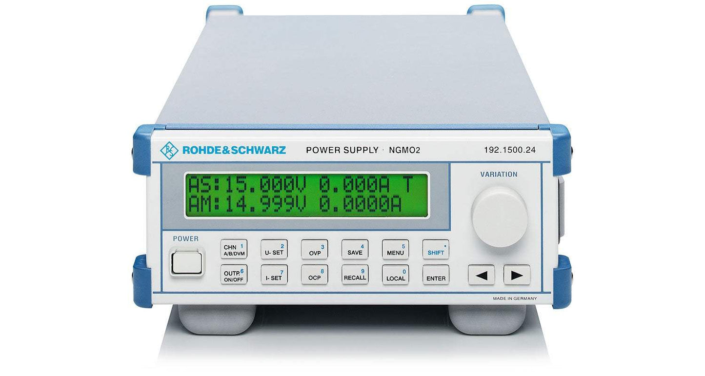
The Dual-Channel Analyzer/Power Supply NGMO2 from Rohde & Schwarz is more than just a simple power supply for test and measurement applications.
This is shown by its advanced features:
Two independent channels, installed in an enclosure which is ½ 19" wide and only 2 U high, guarantee a simple and accurate power supply for battery-operated mobile-radio products now and in the future.
Numerous analysis functions extend the functionality of conventional power supplies. And, it is not just development engineers who will value this instrument. In production environments in particular two things are important: speed and reliability. The NGMO2 has both, coupled with high accuracy which is essential if results are to be reproducible.
Interfaces
The NGMO2 can be remote-controlled via the three main, standard interfaces IEC/IEEE bus, RS-232-C and USB. It has a number of additional I/O channels that can be used to good effect when every extra operation performed by a PC or an internal microcontroller could cause an overload or simply lead to unwanted delays. Each channel has a fast output inhibit to rapidly turn a preset voltage on or off. This may be necessary to test, for example, power semiconductors to prevent destruction by overheating. Not only can the integral, fast current-transient recorder be triggered by internal trigger thresholds for the output current, it also has an external trigger input so that synchronization can be effected using external trigger signals. Although the digital signal processor in the NGMO2 is fast enough to ensure minimal setting and read times for IEC/IEEE-bus programming, the last microsecond delay can be eliminated by directly providing a complete output signal.
Critical test environments involving pulsed current drain, e.g. GSM mobile phones
Power-saving transmission technologies have been, and will continue to be, the key to expanding the capabilities of mobile radio. These improvements are a challenge to both test engineers and test equipment. This is particularly true of transmission technologies that make use of time division multiplexing, for example GSM or TDMA, and also applies to the “slotted mode” used for CDMA – in both cases power supplies have to meet special requirements. On production lines, the use of switching matrices, adapters and leads means that cables up to six meters in length can be found between the power supply and the actual DUT. Cable flexibility must be adequate, which means that the force-line cross section cannot be as large as it should be. And then there are the rise and fall times caused by mobile phones taking their power in pulses: these times can be tens of μs. The inductance of the conductors in the cables causes significant voltage drops.
The power supply must, therefore, be capable of compensating for any voltage drops across the terminals of the mobile phone’s battery. Compensation has to be performed extremely rapidly to be effective. If not, the under voltage detector in the mobile will simply turn the phone off. NGMO2 can meet the challenges described above without any hint of output voltage instability.
Emulation of various battery types and charging states
Mobile, electronic communication equipment is usually battery-operated. If power supply units are used to replace batteries during production, highly satisfactory results are obtained with power supplies with optimized regulation. There is, however, one drawback with this approach: as a power supply’s internal resistance is usually fixed, it is an ideal case that is being simulated, i.e. that of a fully charged battery. As a battery discharges, its internal resistance continuously increases. This means that the voltage across the DUT drops. To maintain its transmit power, a GSM mobile phone, for example, increases its current drain which in turn produces an even greater voltage drop along the power leads and across the battery’s internal resistance which is already very high. This can lead to a vicious circle. The internal supply voltage conditioning of the circuit under test must be capable of reliably handling voltage drops of this kind without causing the phone to malfunction. The NGMO2 can be used to emulate this critical case as its output impedance is adjustable. This also means that different types of batteries (NiCd, NiMH, Li-ion, Li-polymer, etc.) can be emulated to a certain extent. This guarantees that nothing can happen to invalidate tests despite the general trend to lower supply voltages.
Current-/voltage transient analysis
The integral current-transient recorder is a very useful tool for analyzing DUT faults. For example, conclusions can be drawn about whether or not the subassemblies to be tested are functioning properly by forming the differences of the measured current drain of a sequence of signals occurring in rapid succession. For example, a DECT mobile telephone: in this case, the current-drain curve over a complete frame can be recorded using a very high time resolution. When the telephone manufacturer knows at which points in time certain subassemblies (complete phone, power amplifier, mixer, receiver, display etc.) are activated or deactivated, defective partial clusters can easily be found without using additional, complex test equipment.
The reproducibility of pulse current measurements can be improved even further by not just reading one frame and analyzing it, but instead pin-pointing a specific section of interest and reading it. This measurement is repeated several times in succession and the average taken. The section to be investigated is determined by means of the programmable sampling rate and the number of samples. The trigger point for the transient recorder can be defined with an adjustable current trigger threshold. This means that only relevant information is saved to the sample memory. By limiting the number of samples, it is also possible to optimize the transfer rate when samples are being read. It goes without saying that long-term monitoring (current drain) can also be performed on DUTs by choosing sampling intervals of the appropriate length so that the effect of other operating parameters on current drain can be investigated.
However, power consumption is also becoming more and more critical for subassemblies which are not battery-operated. Operating modes such as idle, sleep or power down are being encountered more frequently in electronic equipment because higher clock frequencies coupled with an increasing level of integration are making it impossible to ignore efficient energy management. Using a high-resolution current-transient recorder, like the one already installed in the NGMO2, these modes can be checked using methods similar to those described above.
In addition to current transients, the NGMO2 is able to record voltage transients.
Recording characteristics of semiconductor components
The NGMO2 has two completely identical supply and measurement channels. This means that this small power supply unit can be used to form the basis of an independent parameter test setup for semiconductor components. The NGMO2 can also handle up to four relays and respond to remote control commands. As each channel has an inhibit input, if required, a pulsed supply voltage can be fed to the components to prevent overheating during tests or to simulate a standard pulsed operating mode (e.g. TDMA power amplifier).
Model No
NGM02
Condition
Used
Manufacturer
Rohde & Schwarz
Current
2.5 A
Voltage
15 V
Power
150 W
30+ Years in Business
Secure Payments
Sell Test Equipments
Knowledgeable Staff
On-site Lab
30+ Years in Business
Secure Payments
Sell Test Equipments
Knowledgeable Staff
On-site Lab
Hey👋Let's start with your email
 Chat Live
 Contact Us
 sales@valuetronics.com