


Additional Features:
- This platform may operate as NSG 9000, a powerful Network Services Gateway or as bNSG 9000, an augmented Broadcasting Network Gateway.
- The NSG 9000 comes with either an AC power supply or –48 VDC power supply. All types of the NSG 9000 platform are intended to be installed in restricted access locations.
Chassis
- 2-RU, mounts in Electronic Industries Association (EIA) standard rack
- Hot-swappable Front Panel: The front panel module includes four cooling fans, LCD display panel and a keypad, and indication LEDs. The module may be removed for maintenance purposes while the system is operational.
- Indication LEDs: 2 power, alarm and 9 output status LEDs
Processing module
- 6 x GbE input ports (3 active & 3 backup): Provides three independent ports receiving simultaneously different feeds
- Only three ports are simultaneously active
- Input rate of up to 1000 Mbps per port
- 1 x ASI monitoring port: ASI monitoring port can be configured to output the same data as a selected QAM-RF output TS. The ASI Port can be configured to monitor any output TS.
- Back panel LEDs: Activity and alarm LED pair for each GbE port (12 LEDs in all)
- 10Base-T/100Base-T Ethernet ports: Two independent Ethernet ports, typically used for management (ETH1) and scrambling (ETH2)
QAM-RF module
- Hot-swappable: Up to 9 QAM-RF modules may be mounted in the chassis. Modules may be added or removed while the system is operational.
QAM-RF modules
- Up to nine QAMRF modules, with 2x QAM-RF ports per module
- Overall, the system includes up to 18 QAM-RF ports, capable of carrying up to 72 QAM-RF channels
- Each port carries up to four QAM channels combined and upconverted.
QAM Mode:
- ITU-T J.83 Annex-A (DVB): 8 MHz
- ITU-T J.83 Annex-B: 6 MHz
- ITU-T J.83 Annex-C (Japan): 6 MHz
QAM Constellations:
- ITU-T J.83 Annex-A:16, 32, 64, 128, 256
- ITU-T J.83 Annex-B: 64, 256
- ITU-T J.83 Annex-C:16, 32, 64, 128, 256
Maximum output bit rate
ITU-T J.83 Annex-A
- Up to 3xQAM channels per physical port (Triple QAM)
- Up to 6xQAM channels per module
- Max output bitrate per QAM channel-51.287 Mbps
ITU-T J.83 Annex-B:
- Up to 4xQAM channels per physical port (Quad QAM)
- Up to 8xQAM channels per module
- Max output bitrate per QAM channel-38.811 Mbps
ITU-T J.83 Annex-C:
- Up to 4xQAM channels per physical port (Quad QAM)
- Up to 8xQAM channels per module
- Max output bitrate per QAM channel-39.171 Mbps
Power Supply
AC/DC Power Supply Options
Two distinct types of Power Supply are available:
- AC (input voltage range 85 - 264 VAC)
- DC (input voltage range 36 - 72 VDC)
Hot Swappable redundant power supply: Two independent Power Supply units may be mounted in the chassis. The units can be removed or inserted while the system is operational
Current and load sharing: When operating with two Power Supplies, load is shared and balanced between the two modules.
Physical Dimensions
- Height: 3.47 Inches, 88.1 mm
- Width: 19.00 Inches, 482.6 mm
- Total Length (front to back): 22.88 Inches, 581.2 mm
- Depth (From rack mount fixture to back of device): 21.78 Inches, 553.4 mm
Power Consumption
110V AC
- Max Power consumption (Watts): 490
- Max Steady State Current (Amp): 4.5
- In Rush Current Draw (Amp): 16.7
220V AC
- Max Power consumption (Watts): 400
- Max Steady State Current (Amp): 2.2
- In Rush Current Draw (Amp): 33.5
48V DC
- Max Power consumption (Watts): 450
- Max Steady State Current (Amp): 9.4
- In Rush Current Draw (Amp): 20
Environmental Specifications
- Operating temperature: 0 to 50 °C (32 to 122 °F)
- Storage temperature: –20 to 80 °C (–4 to 176 °F)
- Relative humidity: Maximum 95% non-condensing
Ventilation
- If units are installed in a closed rack, the rack must be ventilated to ensure proper cooling of the units.
Ventilation rate must be:
- At least 1.0 cubic meter per minute (35 cubic feet per minute) per NSG 9000 unit.
- Ventilation rate must be at least 2.2 M3/min (78 CFM) per NSG 9000 unit. This is the air flow through the unit while fans operate at full speed.
Stream Processing Overview
The NSG 9000 accepts a GbE input, and outputs MPEG data over QAM-RF signal.
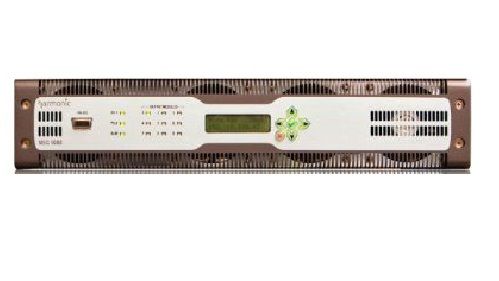
NSG 9000 Front Panel
The front panel of the NSG 9000 platform contains the following:
- Front bezel
- RS-232 connector
- LEDs
- Control panel
- Four cooling fans
Front Bezel
The NSG 9000 platform has a detachable front bezel that snaps on top of the control panel. The air inlets located on the bezel provide air flow.
EIA-232 Serial Port
The EIA-232 serial port may be used to configure the Ethernet port IP addresses. You can use the serial port for monitoring and manual maintenance operations. The EIA-232 serial port has a female DB-9 D-typ connector.
Front Panel LEDs
The front panel of the NSG 9000 platform includes the following LEDs:
- Output Modules LEDs - nine LEDs for monitoring the status of the modules.
- Operation Status LEDs - include two Power supply LEDs and an Alarm LED. The Operation Status LEDs enable to monitor the status of the NSG 9000 power and of the unit’s operation. The LEDs function the same in both standalone and NMX control modes. The following table describes the front panel LEDs, from left to right and from top down.
Control Panel
The control panel consists of an LCD display area and a keypad. The control panel enables preliminary configuration and basic monitoring of the device. It is usually used for standalone devices.
Air Inlets
Air inlets are located along the lower, upper right and middle of the front panel. The air inlets are designed to provide maximum air flow. The air flow is critical for maintaining the proper temperature range. Fans in the front unit draw air in through the front inlets.
Cooling Fans
The NSG 9000 platform uses four fans to control the temperature during operation. The fans located in the front of the device, use air from the front and exhaust it to the rear of the device. Each fan has a speed control and the CPU manages their speed to increase Mean time Between Failures and to lower the noise level.
All four fans are mounted on the back side of the front panel to allow a quick and easy hot swap in case of a fan failure.
Back Panel
The back panel of the NSG 9000 platform includes the following:
- Processing module
- 9 x Module Slots
- 2 x Power supply
- Grounding terminal
Processing Module
The Processing module is the main module of the NSG 9000 platform. It includes the communication interfaces of the unit and the GbE interfaces. The Processing module manages, configures and monitors the device and its modules. It is a swappable module that is easily mounted from the rear side of the platform. The Central Processing module includes the following components:
Ethernet ports
- 2 x DTI ports for M-CMTS application (optional)
- 1 x Clock Test port for future use only
- ASI Monitor port
- Module map
- JTAG - for servicing the device
- 6 x GbE port
Ethernet Ports
Ethernet ports - allow connection to separate networks. The Ethernet ports are labeled ETH1 and ETH2. ETH1 is a management port and ETH2 is for future use. Both ports are 10/100 Base-T ports.
DTI Ports
The DTI ports, labeled DTI1 and DTI2, are optional and are operating once a DTI card is installed. The latter is installed when the NSG 9000 device is operating in an M-CMTS application. You may purchase a device with the DTI card installed or install it by yourself
ASI Monitoring Port
The NSG 9000 platform may duplicate one of the output transport streams to the ASI output port designed for monitoring purposes. Use this port to connect to devices that accept ASI input such as an MPEG analyzer
Module Map
The Module Map is a graphic view of the back panel of the device for ease of use.
GbE Input Ports
The NSG 9000 platform includes six GbE ports labeled GbE 1- 3 and GbE 1 - 3. Three ports support Small Form Factor Pluggable (SFP) transreceivers for either fiber or copper cables and the other three support copper cables for 1000 Base-T cables only.
Any combination of active ports is supported except for the following:
- Copper #1 & SFP #1
- Copper #2 & SFP #2
- Copper #3 & SFP #3
SFP Module
The SFP (Small Form Factor Pluggable) module converts optical data into electrical data and vice versa. The SFP modules allow the NSG to receive input signals over a variety of physical interfaces:
- Single-mode optical interface (1000 Base-LX)
- Multi-mode optical interface (1000 Base-SX)
- Copper interface (1000 Base-T)
Module Slots
The back panel of the NSG 9000 platform includes nine module slots labeled Module 1 to nine. Each one of the slots accommodates a single QAM-RF module.
QAM-RF Modules
Each QAM-RF module performs QAM modulation and up conversion of the QAM signal. Each QAM-RF module includes two QAM-RF ports labeled 1 and 2. Each port may output up to four channels as your license permits
Each module may be configured offline and when mounted into the slot, the system identifies the inserted module. The modules are hot swappable and are mounted and plugged from the rear side of the device.
Power Supply
The NSG 9000 device is furnished with two hot swappable redundant AC or DC power supply units. Each power supply unit easily accommodates the power consumption of a fully populated device. When both power supply units are plugged in and connected to the mains, the power supply units operate in current sharing mode.
AC Power Supply
- Physical Dimensions: 40mmH x 90mmW x 440mmD
- Input voltage: 85-264 VAC
- Line frequency: 47–63 Hz
-48 VDC Power Supply
- The -48 VDC power supply unit is supplied with the required 3-pin male connector
- Physical Dimensions: 40mmH x 90mmW x 440mmD
- Input voltage: 36 - 72VDC
- Maximum Operating Current: 16A
| Manufacturer | Harmonic |
|---|---|
| Condition | Used |