


Features:
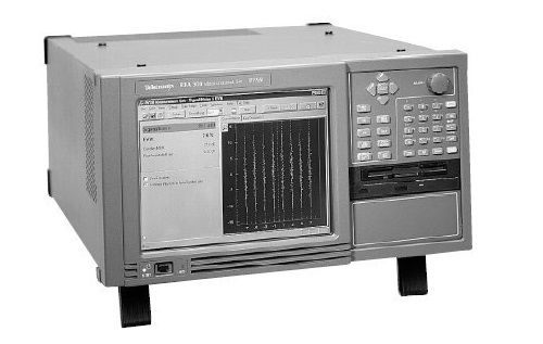
- RFA300A: RF Transmission Monitor; Measurement Set 8VSB
- Interactive and Automated Measurements Helps You Identify Degradations in 8VSB Transmitter and Efficiency Before They Become Quality and Reliability Problems
- Proprietary Nonlinearity and In-Service Phase Noise Measurements Give You Unique Insight Into Transmitter Performance and Helps Identify Sources of Quality or Reliability Problems
- User Programmable Limits Mask Lets You Ensure Your 8VSB Transmission Conforms to Regulatory Standards and the Operational Parameters You Establish
- Two Switchable RF Inputs Support Close-Loop Correction of 8VSB Transmitters
- A Graphical User Interface with One Touch Operation Reduce the Time and Effort Needed to Perform Installation Checks, Routine Maintenance, or Troubleshooting
Applications
- 8VSB Transmitter Installation
- Continuous Monitoring of 8VSB Transmitters with Limits Checking
- Repair and Maintenance of 8VSB Transmitters
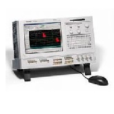
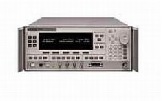
The Tektronix RFA300A provides fast, easy and efficient solutions for 8VSB RF measurement needs while delivering the measurement accuracy and ease of use you've come to expect from Tektronix. The range of capabilities offered by the RFA300A includes all measurement functions required to install, operate and maintain an 8VSB transmitter.
The RFA300A brings the heritage of the Tektronix VM700 to RF measurements for 8VSB DTV transmitters. The RFA300A provides a suite of measurements that permit the user to examine or measure important DTV parameters including constellation, eye diagram, peak to average power ratio, linear errors and non-linear distortion. Measurement displays provide numeric data augmented with easy to interpret graphics which allow the operator to visually determine operational performance of the transmitter.
The RFA300A can measure individual operating parameters or provide continuous monitoring of transmitter operation with notification if user-selectable limits are violated.
Measurements
Signal/Noise Ratio, Error Vector Magnitude, Complex Modulation Error Ratio, Pilot Amplitude Error with Constellation Display and Eye Diagram Graphics.
Signal/Noise, the ratio of the ideal real axis signal power to all other contributions (noise, distortion, etc.), is an all-in-one quality measurement of the 8VSB signal. Error Vector Magnitude is the square root of the mean complex relative noise power divided by the real (in-phase) part of the outermost constellation state. Modulation Error Ratio is a complex form of the Signal/Noise measurement, which is made by including quadrature channel information in the ideal and error signal computations.
Out-of-channel emissions are spectral power vs. frequency measurements similar to those made by a spectrum analyzer. The measurement is made and scaled in accordance with the complex, FCC specified method. The RFA300A measures to >-80 dB on the FCC scale.
Transmitter Frequency Response Error measurements are plots of the transmitter's spectral amplitude vs. frequency with respect to the ideal 8VSB root-cosine transmitter curve.
Transmitter Group Delay Error measurements are plots of the transmitter's group delay response as a function of frequency.
Amplitude Error is the difference between the transmitter's actual vs. its ideal instantaneous output amplitude. This difference is plotted vs. the ideal instantaneous signal amplitude, resulting in a display of the transmitter's dynamic power linearity. Phase Error similarly plots the carrier's phase angle error as a function of instantaneous signal amplitude. These nonlinear distortion measurements are unique to the RFA300A.
The In-service Phase Noise measurement displays the transmitter's Phase Noise characteristics. Normally only available as an out-of-service measurement, in-service phase noise is an RFA300A proprietary measurement.
Peak to Average power ratio displays the statistical amplitude distribution of the transmitter's signal. It is another way of determining the transmitter's power linearity.
Simple Operation
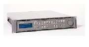
Operation of the RFA300A is extremely user-friendly. No detailed 8VSB knowledge is required to make accurate measurements. The high-resolution color display provides a clear view of measurement results and waveforms. A VGA output is also provided to drive an external monitor. Instrument control is by mouse, a VM700-like touch screen, front panel buttons and knob or by keyboard entry. Key parameters and measured values are displayed in easy to read form, both numerically (in large text) and graphically.
Signal Monitor Mode
- Unattended monitoring of 8VSB signals
- User-specified limits (Two levels, Caution and Alarm)
- Notification when limits or masks are exceeded
- Notification to control point or local (Dry Contact Closure)
Printing
- All devices supported by Windows NT® (serial or parallel)
| Manufacturer | Tektronix |
|---|---|
| Condition | Used |