


Additional Features:
- Bandwidth: 500 MHz
- Number of Channels: 4
- Simultaneous Channels: 4
- Simultaneous Maximum Sampling Rate/ch: 1 GSa/s
- Maximum sampling rate: 2 GSa/s
- Max. Record Length: 50, 000 pt/sec
- Min. Vertical Sensitivity: 1 mV/div
- Maximum Vertical Sensitivity: 10 V/div
- Channel to Channel Delay: 50 ps
- Rise time: 700 ps
- Number of Bits: 8 bits
- Input Impedance: 1 MOhm
- Input Impedance (alternate): 50 Ohm
- Input Coupling: AC, DC, GND
- Maximum Input Voltage: 400 Vrms
- Main time base: lowest: 500 ps/div
- Main time base: highest: 10 s/div
- Timebase accuracy: .0025 %
- Trigger Source: External, Internal
- Trigger Modes: Auto, Edge, Logic, Normal, Pulse, Single
- Minimum Glitch Trigger: 1 ns
- Color LCD
- Display Size: 17.78 cm
- Display modes: Dot, Persistence, Vector
- User Interface: Proprietary
- Ports to Peripheral Devices: Centronics, GPIB, RS232
- Test Pattern Storage: 10 Patterns
- Novram data storage: Yes
- Data Storage Type: FDD
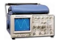
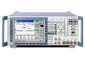
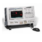
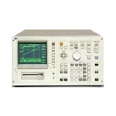
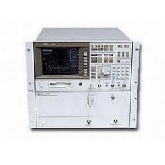
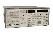
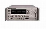
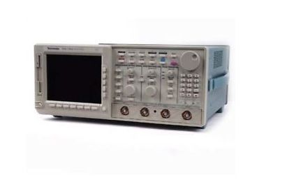
The Tektronix TDS744 oscilloscope is a graph-displaying device – it draws a graph of an electrical signal. In most applications, the graph shows how signals change over time: the vertical (Y) axis represents voltage and the horizontal (X) axis represents time. The intensity or brightness of the display is sometimes called the Z axis.
The Tektronix TDS744 oscilloscope's simple graph can tell you many things about a signal, such as: the time and voltage values of a signal, the frequency of an oscillating signal, the “moving parts” of a circuit represented by the signal, the frequency with which a particular portion of the signal is occurring relative to, other portions, whether or not a malfunctioning component is distorting the signal, how much of a signal is direct current (DC) or alternating current (AC) and how much of the signal is noise and whether the noise is changing with time.
The TDS744 has a combination of front-panel buttons, knobs, and on-screen menus to control the many functions of the oscilloscope. The front-panel controls are grouped according to function: vertical, horizontal, trigger, and special. Set a function you adjust often, such as vertical positioning or the time base setting, directly by its own front-panel knob. Set a function you change less often, such as vertical coupling or horizontal mode, indirectly using a selected menu.
Menus
Pressing one (sometimes two) front-panel button(s), such as vertical menu, displays a main menu of related functions, such as coupling, bandwidth, etc., at the bottom of the screen. Pressing a main-menu button, such as coupling, displays a side menu of settings for that function, such as AC, DC, or GND (ground) coupling, at the right side of the screen. Pressing a side-menu button selects a setting such as DC.
Indicators
On-screen readouts help you keep track of the settings for various functions, such as vertical and horizontal scale and trigger level. Some readouts use the cursors or the automatic parameter extraction feature (called measure) to display the results of measurements made or the status of the instrument.
General Purpose Knob
Assign the general purpose knob to adjust a selected parameter function. More quickly change parameters by toggling the SHIFT button. Use the same method as for selection a function, except the final side-menu selection assigns the general purpose knob to adjust some function, such as the position of measurement cursors on screen, or the setting for a channel fine gain.
GUI
The user interface also makes use of a GUI, or Graphical User Interface, to make setting functions and interpreting the display more intuitive. Some menus and status are displayed using iconic representations of function settings. Such icons allow you to more readily determine status or the available settings.
Signal Acquisition System
The signal acquisition system provides four, full-featured vertical channels with calibrated vertical scale factors from 1 mV to 10 V per division. All channels can be acquired simultaneously.
Each of the full-featured channels can be displayed, vertically positioned, and offset, can have their bandwidth limited (250 MHz or 20 MHz) and their vertical coupling specified. Fine gain can also be adjusted.
Besides these channels, up to three math waveforms and four reference waveforms are available for display. A math waveform results when you specify dual waveform operations, such as add, on any two channels. A reference waveform results when you save a waveform in a reference memory.
Horizontal System
There are three horizontal display modes: main only, main intensified, and delayed only. You can select among various horizontal record length settings.
A feature called "Fit to Screen" allows you to view entire waveform records within the 10 division screen area. In other words, waveforms are compressed to fit on the screen.
Both the delayed only display and the intensified zone on the main intensified display may be delayed by time with respect to the main trigger. Both can be set to display immediately after the delay (delayed runs after main mode). The delayed display can also be set to display at the first valid trigger after the delay (delayed-triggerable modes).
The delayed display (or the intensified zone) may also be delayed by a selected number of events. In this case, the events source is the delayed-trigger source. The delayed trigger can also be set to occur after a number of events plus an amount of time.
Trigger System
The triggering system supports a varied set of features for triggering the signal-acquisition system. Trigger signals recognized include Edge, Logic, and Pulse. Video is available with Option 5: Video Trigger
You can choose where the trigger point is located within the acquired waveform record by selecting the amount of pretrigger data displayed. Presets of 10%, 50%, and 90% of pretrigger data can be selected in the horizontal menu, or the general purpose knob can be assigned to set pretrigger data to any value within the 0% to 100% limits.
Acquisition Control
You can specify a mode and manner to acquire and process signals that matches your measurement requirements:
Select the mode for interpolation (linear or sin(x)/x). This can increase the apparent sample rate on the waveform when the maximum real-time rate is exceeded.
Use sample, envelope, and average modes to acquire signals. You can also use high-resolution and peak-detect modes.
Set the acquisition to stop after a single acquisition (or sequence of acquisitions if acquiring in average or envelope modes) or after a limit condition has been met.
Select channel sources for compliance with limit tests. You can direct the TDS to signal you or generate hard copy output either to a printer or to a floppy disk file based on the results. Also, you can create templates for use in limit tests.
On-Board User Assistance
Help and autoset can assist you in setting up the TDS744 to make your measurements.
Help displays operational information about any front-panel control. When help mode is in effect, manipulating any front-panel control causes the TDS744 to display information about that control. When help is first invoked, an introduction to help is displayed on the screen.
Autoset automatically sets up the TDS744 for a viewable display based on the input signal.
Measurement Assistance
Once you have set up to make your measurements, the cursor and measure features can help you quickly make those measurements.
Cursor
Three types of cursors are provided for making parametric measurements on the displayed waveforms. Horizontal bar cursors (H Bar) measure vertical parameters (typically volts). Vertical bar cursors (V Bar) measure horizontal parameters (typically time or frequency). Paired cursors measure both amplitude and time simultaneously. These are delta measurements; that is, measurements based on the difference between two cursors.
Both H Bar and V Bar cursors can also be used to make absolute measurements. For the H Bars, either cursor can be selected to read out its voltage with respect to any channels ground reference level. For the V Bars, the cursors measure time with respect to the trigger point (event) of the acquisition. The cursors can also control the portion of the waveform on which automatic measurements are made. For time measurements, units can be either seconds or Hertz (for1/time).
Measure
Measure can automatically extract parameters from the signal input to the TDS744. Any four out of the 25 parameters available can be displayed on the screen. The waveform parameters are measured continuously with the results updated on-screen as the TDS744 continues to acquire waveforms.
Digital Signal Processing (DSP)
An important component of the multiprocessor architecture of the TDS744 is the DSP. This dedicated processor supports advanced analysis of your waveforms when doing such compute-intensive tasks as interpolation, waveform math, and signal averaging. It also teams with a custom display system to deliver specialized display modes.
Storage
Acquired waveforms bay be saved in any of four nonvolatile REF (reference) memories or on a 3.5 inch, DOS 3.3-or-later compatible disk. Any or all of the saved waveforms may be displayed for comparison with the waveforms being currently acquired.
The source and destination of waveforms to be saved may be chosen. You can save any of the four channels to any REF memory or move a stored-reference from one REF memory to another. Reference waveforms may also be written into a REF memory location via the GPIB interface.
I/O
The TDS744 is fully controllable and capable of sending and receiving waveforms over the GPIB interface (IEEE Std 488.1-1987/IEEE Std 488.2-1987 standard). This feature makes the instrument ideal for making automated measurements in a production or research and development environment that calls for repetitive data taking. Self-compensation and self-diagnostic features built into the TDS744 to aid in fault detection and servicing are also accessible using commands sent from a GPIB controller.
Display
The TDS744 offers flexible display options. You can customize the following attributes of your display:
- Color: Waveforms, readouts, graticule, and variable persistence with color coding
- Intensity: waveforms, readouts, and graticule
- Style of waveform display(s): vectors or dots, intensified or non-intensified samples, infinite persistence, and variable persistence with color coding
- Interpolation method: Sin(x)/x or Linear
- Display format: xy or yt with various graticule selections including NTSC and PAL to be used with video trigger (option 05)
Zoom
The TDS744 also provides an easy way to focus in on those waveform features you wish to examine up close. By invoking zoon, you can magnify the waveform using the vertical and horizontal controls to expand (or contract) and position it for viewing.
| Manufacturer | Tektronix |
|---|---|
| Condition | Used |
| Channels | 4 |
| Frequency | 500 MHz |
| Record Length | 50 kPts |
| Sampling Rate | 2 GS/s |