


Additional Features:
- Digital Waveform Monitor
- Digital Vectorscope
- Group delay and frequency response
- Noise Measurement Set
- Automatic Measurement Set
Auto Mode
- Unattended monitoring of PAL video signals from studios, STLs, Earth Stations, and transmitters
- User-specified limits
Measure Mode Provides Graphic Display of Measurements
- Measure mode provides graphic display of measurements: K factor, differential gain and phase, luminance to chrominance delay, noise spectrum, group delay with (sin x)/x, color bars
- Relative to reference on most measurements
- Configurable for all standard test signals
- Three input channels
- Channel difference modes
- Averaging on all measurement modes
- Picture mode for source ID
- Hardcopy for analysis and documentation
- Remote control operation
Power Requirements
- Mains Voltage Range: 90 to 132 VAC or 180 to 250 VAC
- Mains Frequency: 47 Hz to 63 Hz
- Power Consumption: 250 Watts
- Fuse: 115VAC: 6A, 250V Slow Blow, 0.250 X 1.250; 230VAC: 3A, 250V, Slow Blow, 3AG, MSL-3
- EMI: Meets FCC CFR Part 15, Sub-part B, Class A
Remote Relay
- Remote Contact Closure Relay: Contacts are not debounced
- Maximim Current: 50mA
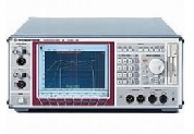
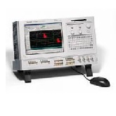
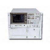
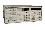
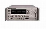
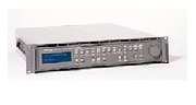
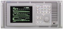
The Tektronix VM700A is a complete video monitoring and measuring instrument which can be used for automatic measurements and monitoring, as well as for manual measurements. The user can select a display of numeric values to confirm the quality of the signal path, or may select graphic displays for more detailed analysis.
The VM700A Auto Mode makes standard video measurements automatically, including those specified in CCIR Rep. 624-1, Rec. 567, and Rec. 569. These measurements can be compared with user-defined limits. A caution or alarm message is generated when these limits are violated. Reports can be made and printed automatically at operator scheduled times.
For a more detailed analysis of the waveform, the actual signal may be displayed and additional measurements made manually. In Waveform Mode, cursors are available to aid in measuring time, frequency and amplitude. These cursors allow a very quick and precise location of the 10%, 50% and 90% points on any transition. Enabling cursors also enables an automatic calculation in the waveshape in the center of the display. The parameters calculated are sine peak-to-peak amplitude, frequency, and offset from blanking level. This is very useful for frequency response measurements with the multiburst signal.
The waveform display can be expanded around any point both vertically and horizontally. Since the data is digitized, the display remains bright at all expansion factors. The scales automatically expand with the waveform, so all units are correct as displayed. A channel difference mode (A-B, A-C, B-A, B-C, C-A, and C-B) is also provided.
A screen memory selection enables Envelope Mode, which is useful for looking at teletext, jitter, or other changes over time.
The Vector Mode provides the normal vectorscope display. The vectors may be rotated or expanded, with the rotation angle and gain values displayed numerically on the screen.
A unique "Find Colorbars" feature searches all video for colorbars and displays the vectors if found. The vectors can be referenced to either the selected channel's burst or the burst of one of the other two channels or continuous subcarrier. The phase difference between the selected channel and the reference is always displayed.
Select Line in both Waveform and Vector modes can be used to quickly specify any line for display or automatic measurement if it is the proper signal.
Measure Mode provides graphic displays of measurement such as noise spectrum, group delay, and K factor, for adjustments or closer analysis of the measurement. Most measurements can be made relative to a stored reference to eliminate or minimize signal source errors. Most measurements have averaging to reduce the effect of noise. A channel difference mode (A-B, A-C, and B-C) is also provided and is useful in input to output analysis of a device.
The signal source can be quickly verified using the picture display. Any line may be selected on the picture for viewing in the waveform or vector displays.
The user can define a sequence of operations as a new function. For example, the measurements to be made on a transmitter demodulator video output could be identified with a function labeled DEMOD. A user would simply select this function to make all measurements, and provide a printout. The Tektronix VM700A stores user defined functions as editable ASCII files.
All information on the screen may be printed on printers supporting PostScript, HP LaserJet, or 24-pin Epson graphics via the standard RS-232C interface. Automatic measurement results can be printed on most ASCII printers using the same interface.
The Tektronix VM700A can be operated from a remote terminal via RS-232C to monitor unattended transmission systems and/or put systems under computer control. In addition, all files could be uploaded to a main computer, and downloaded to other VM700As. Two different protocols are supported: FTP (File Transfer Protocol) and TELNET. The user can also select a "no Protocol" mode of the RS-232C interface when dealing with low baud rates. However, file transfers can only take place with FTP.
| Manufacturer | Tektronix |
|---|---|
| Condition | Used |
| 01 | NTSC Measurements |
|---|---|
| 11 | PAL Measurements |
| 30 | Component Measurements |
| 40 | Audio Measurement Module |
| 48 | GPIB Interface |
- Tektronix VM700A Operator Manual
- Tektronix VM700A Programmers Reference Manual
- Tektronix VM700A Service Manual