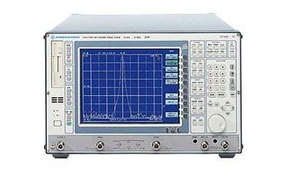
The Rohde and Schwarz ZVC comprises a test set with two directional couplers, an RF switch, two measurement channels and - unlike ZVRE and ZVCE - two reference channels. With this configuration a variety of novel calibration procedures, eg TNA, can be performed, which considerably improve the accuracy particularly in non-coaxial applications. The ZVC is the allrounder of the family and suitable for applications in R&D and production no matter how sophisticated.
Test sets
The 8 GHz models ZVCE and ZVC are always equipped with 50 W active test sets. Depending on the model, the test sets comprise one or two power splitters, an electronic switch and one or two SWR bridges or directional couplers. Additional step attenuators (0 dB to 70 dB, components marked red in the drawings below) can be inserted into the generator paths and the two measurement channels to extend the power range of the receivers to +27 dBm and to lower minimum output power to -95 dBm. When the test sets are fitted with attenuators and the External Measurements option (components marked green in the drawings below), generator and receiver can be alternatively switched to three ports on the front panel (OUTPUT a1, INPUT b1, INPUT b2). This increases output power, sensitivity and dynamic range, and measurements down to 10 Hz can be performed with the 4 GHz models. In addition, the flexibility on external test sets, e.g. using an external pre-amplifier, is enhanced. The Reference Channel Ports (components marked blue in the drawings below) allow to feed the signal for the reference channel a1 from outside. This feature facilitates e.g. phase measurements on frequency converting devices. The test ports are fitted with female N connectors.
Speed >>25 sweeps/s
The extremely low-noise and fast synthesizer in conjunction with an exceptionally large measurement bandwidth of up to 26 kHz allows real - time result display. The ZVx measures not in two subsequent sweeps but at every frequency point in forward and backward direction and thus all four S-parameters - including system error correction. This ensures real-time display of fully corrected data even during alignments with reduced sweep speeds. The dynamic range of ZVx is more than 95 dB even at a high measurement rate of 25 sweeps/s and 10 kHz measurement bandwidth.
Dynamic range >130 dB
The high stopband and low passband attenuation of modern RF components place new demands on network analyzers. Thanks to fundamental mixing, the useful dynamic range of Rohde & Schwarz network analyzers is more than 25 dB better than with conventional sampling techniques. Because of the low-noise front end, Rohde & Schwarz network analyzers attain a dynamic range of >130 dB, so transmission measurements on DUTs with extremely high stopband attenuation can be performed with high accuracy, even at low input levels.
Power calibration: testing active DUTs
Power calibration performed in the factory enables constant output power and high accuracy in the measurement of absolute input level over the full frequency range. This is particularly important for frequency-converting measurements and non-linear measurements on active components. Furthermore, frequency-dependent level variations of an external test setup can be measured and compensated with the aid of the Power Calibration option.
Simultaneous display of four traces on the 26 cm color LCD
The ZVx models are the first network analyzers in this price class to simultaneously display up to four measurement traces with independent parameters (measured quantity, frequency range, bandwidth, etc). The large, active color LCD with high refresh rate allows precise alignments without operator fatigue.
Internal PC
The network analyzers are equipped with a PC board including interfaces for keyboard, mouse, printer, external monitor and WindowsNT as the operating system. In the PC mode, the internal hard disk can be accessed and PC programs executed on the ZVR. This function considerably simplifies operation, processing and result recording. The optional Ethernet link, the integration of any printer driver and the execution of IEC/IEEE bus control programs on ZVR considerably extend the application range and performance. Complete setups, traces, numerical results, limit lines, calibration data, macros and screenshots can be stored on the hard disk or on floppy disks. The available formats (e.g. WMF, ASCII, Serenade....) allow problem-free import to Windows programs. The data can be processed in the ZVR with the aid of the internal PC.
Automatic test systems
Fast recording and processing of measured data and, in addition, an SCPI-conformal IEC/IEEE bus command set make all models of the ZVR family ideal for use in automatic measurement systems. All models are equipped with two IEC/IEEE bus interfaces as standard. One is used for analyzer control via an external PC, the other for controlling external devices, e.g. signal sources for intermodulation or mixer measurements, from the ZVR. Another optional IEC/IEEE bus interface is provided for the internal PC. Via this interface, IEC/IEEE control programs can be executed on the internal PC, thus enabling the ZVR to control itself or complete test systems. The Ethernet option allows data exchange and control via LAN.
Efficient calibration techniques
The classic 12-term calibration method requires four calibration standards: Through, Open, Short and Match. The name TOSM given to this method is an abbreviation of the standards' names. A number of other modern calibration methods (TOM, TRM, TRL, TNA) are also provided in ZVR and ZVC. Unlike TOSM (12-term) they require only three different standards. Additionally, lines (L), reflecting one-ports with unknown reflection coefficient (R), matched attenuators (A) and two-port networks (N) with symmetrical reflection can be used. Due to its simplicity, TOM is the method recommended for general applications. For calibration at frequencies up to 100 MHz it is not even necessary to connect an open circuit, and the ports may simply be left open. Thus, a complete two-port calibration can be performed with only two calibration standards. TOM allows also implicit verification so that errors caused by defective calibration kits or operating errors are excluded. This considerably enhances reliability in the laboratory and particularly in production.
With on-wafer measurements, measurements on PCBs or in fixtures it is difficult to design or specify suitable calibration standards at justifiable effort. This problem can be solved with the TNA and TRM calibration methods developed and patented by Rohde& Schwarz. With these methods the characteristics of the calibration standards need not be fully known. With TNA, for instance, a full two-port calibration can be performed with two standards: if reflection symmetry is provided at the reference planes, the calibration step with network (N) does not require a standard to be connected, the test ports can just be let open. Just a through (T) with known length and a matched attenuator (A) are required.
The calibration effort is reduced to a minimum when the AutoKal option is used that requires only one simple through-connection.
Model No
ZVC60
Condition
Used
Manufacturer
Rohde & Schwarz
Frequency
8 GHz
B10
Increased Output Power for Port1 or Output a 1
B17
Second IEC BUS Interface
B21
Generator Step Attenuator PORT1
B22
Generator Step Attenuator PORT2
B23
Receiver Step Attenuator PORT1
B24
Receiver Step Attenuator PORT2
B25
External Measurements
B4
Mixer Measurement
B5
Nonlinear Measurements
B6
Reference Channel Ports
B7
Power Calibration
30+ Years in Business
Secure Payments
Sell Test Equipments
Knowledgeable Staff
On-site Lab
30+ Years in Business
Secure Payments
Sell Test Equipments
Knowledgeable Staff
On-site Lab
Hey👋Let's start with your email
 Chat Live
 Contact Us
 sales@valuetronics.com