


Additional Features:
- 12.5 Gb Clock Recovery Instrument
- Instrumentation quality clock recovery
- 150 Mb/s–12.5 Gb/s continuous data rate coverage
- Accurate variable loop bandwidth from 100 kHz to 12 MHz
- Auto lock capability with LED display
- Programmable peaking adjustment with first and second order rolloff capability
- Self-measured and displayed PLL frequency response
- USB control connection to BERTScope or stand alone operation via front panel
- Single-ended or differential 50 Ω data inputs/outputs
- DC coupled data through path
- Full and divided clock outputs with selectable divide ratios
- Measurement of clock phase deviation as a function of frequency and time
- Data measurement capability
- Edge Density Measurement —determine the mark density of the signal under test
- Ideal for spread spectrum clock (SSC) applications with large frequency excursions
- BERTScope CR Can Be Used with Any Sampling Oscilloscope, BERT or Pattern Generator
- BERTScope CR Works Seamlessly with BERTScope Signal Integrity Analyzer
- You can utilize the clock recovery instrument with the BERTScope Analyzer by connecting the USB cable between the two instruments
- The graphing capability can be displayed on the BERTScope Analyzer by pressing the “To CR analysis” soft key
Many communication standards now specify that jitter testing must be carried out using a reference clock that has been derived from the data signal. Typical phase lock loop (PLL) characteristics are specified in terms of the -3 dB bandwidth of the recovery loop, the rate of rolloff of the frequency response, and the degree of response peaking allowable.
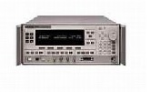
The BERTScope CR’s advanced architecture measures and displays the PLL frequency response from 100 kHz to 12 MHz; the highest loop bandwidth available for jitter testing on the market today. The first clock recovery instruments to allow full control of parameters including loop bandwidth, peaking/damping and rolloff.
Design and test engineers can now find and lock onto signals of undefined or unknown data rate. The engineer can recover full rate clocks, including spread spectrum clocks, for signals at data rates from 150 Mb/s to 12.5 Gb/s. The engineer has full control of key parameters for variable loop bandwidth, peaking/damping and first and second order rolloffs, optimizing jitter tracking.
Many test standards require the use of a Golden PLL (phase lock loop.) Control of the BERTScope CR variable loop bandwidth allows for control of the jitter transferred to the recovered clock. When the loop bandwidth setting is narrow, much of the high frequency jitter is removed from the clock signal. The narrowest LBW setting is desirable when a clock with the lowest possible jitter is required. When the loop bandwidth setting is wide, jitter is transferred to the recovered clock, emulating a clock signal similar to the CDR of the receiver under test. Each standard provides an optimum LBW setting for clock recovery often called the Golden PLL.
The BERTScope CR has been designed from the ground up to provide users with flexibility and accuracy in compliance measurements. The HS model utilizes high sensitivity data inputs (40 mV single ended, 20 mV differential) with buffered data outputs. It is ideal for optical test applications, like 4X/8X Fibre Channel and 10G Ethernet standards, where the signal under test must be split off and converted from optical to electrical before being fed into the clock recovery data input. The BERTScope CR recover a full-rate clock up to 12.5 Gb/s, an important requirement for testing XFP and other 10 Gb/s MSA modules. The BERTScope CR is also the model of choice in electrical applications where the additional data input sensitivity is critical to the test setup.
Spread Spectrum Clocking (SSC) is an increasingly required feature of serial bus standards. When employed, it can prove difficult to track but its effect must be included in test. These instruments are able to track SSC correctly with large frequency excursions up to 5000 ppm, making them unique amongst clock recovery test solutions. The BERTScope CR is the first clock recovery instrument to recover clocks from spread spectrum clocked signals used in Serial ATA, SAS, PCI Express and FB DIMM applications. Spread spectrum clocks exhibit low frequency (30-33 kHz) modulation, for example, resulting in 225 UI deviation when imposed on a 3 Gb/s data signal. This frequency deviation is tracked accurately by the clock recovery instrument when the optional 5 piece cable set is used with the BERTScope CR and BERTScope Analyzer. This cable set is matched to compensate for the 5ns delay in BERTScope Analyzer with SSC signals, thus avoiding jitter amplification.
A signal with SSC was measured with the BERTScope CR. Outputs on the rear panel of the instrument provide monitoring points to view the loop behavior. When viewed on a low-bandwidth, real-time oscilloscope, the triangular waveform characteristic of SSC is visible in the lower trace. The upper waveform displays the difference in phase between data input and clock recovery output.
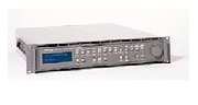
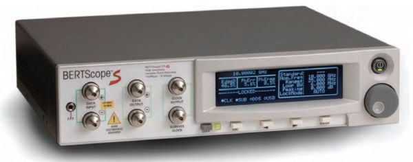
The instruments can be used with the BERTScope Stress Analyzer AND in stand-alone operation. Inexperienced users and experts alike will respond to the same ease and accuracy already available in the BERTScope S Signal Integrity Analyzer. Perfect companions to the BERTScope, the clock recovery instruments smoothly integrate with the analyzer, seamlessly sharing a common user interface. A single USB connection and supplied high-quality microwave coax cables connect the two units together—that is all that is required to start measurements. The BERTScope automatically senses the presence of the Clock Recovery instrument, and control is achieved through the Clock Recovery setup screen. It’s that simple. Additional information is also immediately available on the front panel display, showing parameters such as the PLL bandwidth, lock status, bit rate, peaking and rolloff. The system is designed to make sure that you are always aware of the test conditions, always aware of the factors in play that will affect your measurement results.
Graphing capability on the BERTScope analyzer allows users to plot loop response and inverse response curves for the settings in use, the -3 dB point and peaking values are also measured and clearly displayed.
For engineers wanting to utilize test equipment already available on their lab bench, the BERTScope CR is controllable via the front panel for stand alone operation. In keeping with the BERTScope family’s philosophyof being the easiest to use signal integrity tools available, the clock recovery instrument provides the information you most need, right up front. For easy verification of compliance, the correct characteristics are automatically set when a given standard is selected from a pull-down menu. However, for users wanting to explore the limits of their designs, full control of parameters is also easily available. A good example of this is for systems where restricting the build-up of jitter is critical. Clock recovery plays a crucial role in this, and the ability to emulate a clock recovery source with excessive peaking is a great way of understanding the system sensitivity to jitter gain. The CR hasvariable jitter peaking that goes way beyond simple compliance, and allows jitter gain in excess of 10 dB if desired.
Remote control of the instrument is easily accessible via USB through BERTScope S analyzer. TCP/IP and GP-IB protocol interfaces are supported via USB and software developers kit.
| Manufacturer | SyntheSys Research |
|---|---|
| Condition | Used |